Back in the 1960's and 70's we did this all the time. It was the good days before hydraulic calculation programs or computers when we did everything by hand.
Same thing from the 2013 edition.
(4) New systems exceeding 5000 ft2 (465 m2) where the flows required in Table 11.2.2.1 are available at a minimum residual pressure of 50 psi (3.4 bar) at the highest elevation of sprinkler.
Let's assume light hazard building.
TABLE 11.2.2.1 Water Supply Requirements for Pipe Schedule Sprinkler Systems indicates a minimum flow of 500 to 700 gpm at the base of thee riser. It has always been the lower figure could be used where you have a central station monitoring service. Let's assume we do not have central station, ridiculous because everything new today requires it, but let's assume we don't so we are stuck at 700 gpm.
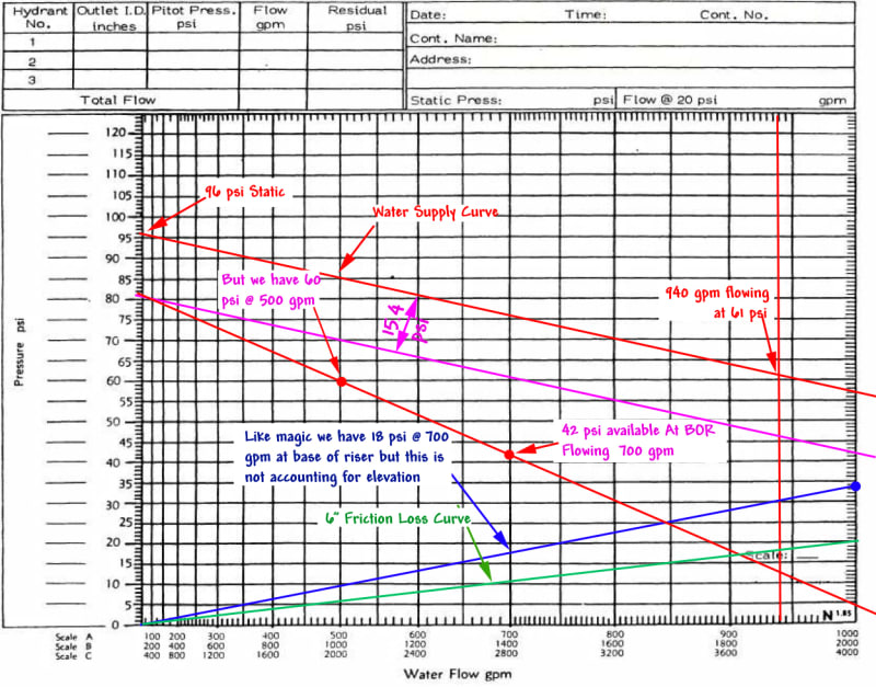
We have a flow test on this dead end main where static at Hydrant A was 96 psi with a residual pressure of 61 psi flowing 940 gpm.
If you are new at this pay attention to the elevations of Hydrant A and the finished floor.
First thing we need do is calculate what our water supply is to the base of the riser.
We need to compensate for the friction loss from Hydrant "A" to the base of the riser. Remember, this is a dead end line so our source would be Hydrant "A
Flowing 1,000 gpm we can expect a loss of 20.8 psi from Hydrant A to 6x4 Tee which is mislabeled as "source". It isn't the source, your source is Hydrant "A".
We're going to draw that with a green line.
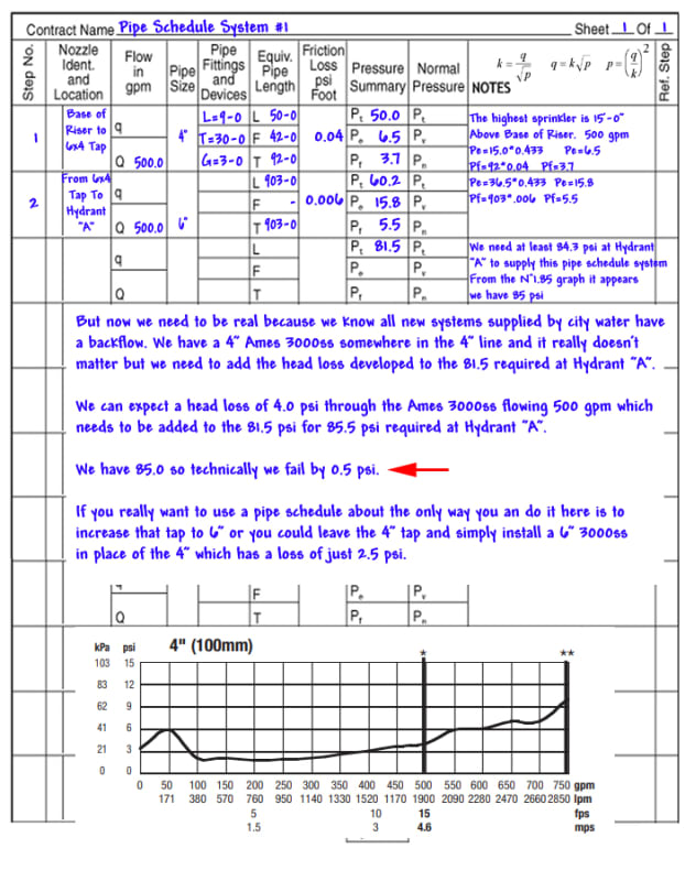
The blue line represents our friction loss through 50' of 4" from the 6x4 Tee to the base of the riser. I figured 5' from the elbow to the Flange and Spigot piece and don't forget we have the equivalent length of a 4" tee, 4" gate valve and 4" elbow for an equivalent length of 43' in fittings plus 50' of pipe for a total of 93'-0".
At 1,000 gpm our loss through the 4" will be 12.5 psi. Put a blue dot at 1,000 gpm at 20.8+12.5 or 33.3 psi which I did in blue. Draw a blue line from 0 psi to 33.3 psi @ 1.000 gpm.
Now all we need do is compensate for the elevation which is 36.5'*.433 psi for a head loss of 15.4 psi. Because there is a rise this line will parallel below the initial water supply curve.
Now all we need do is subtract the 18 psi due to friction loss, at 700 gpm of course, from the 60 psi available after compensating for the the elevation change and to find out we have 42 psi available at the base of the riser flowing 700 gpm.
Byt w
But if we install a central station alarm at 500 gpm we have 60 psi available at the base of the riser.
The only thing left to do is adjust for the height of the highest sprinkler.
If your highest sprinkler is 12'-0" AFF then 12*.433=5.2 psi need to be subtracted from the pressure available.
At 500 gpm we would have 54.8 psi available while only 42-5.2=36.8 psi.
I wish new designers would learn you can solve a lot of problems just by using the N^1.85 graph. Not just solve it but you can see it.
Hopefully I didn't mess up on any of the simple math but if I did you get the idea.


