Continue to Site

Eng-Tips is the largest engineering community on the Internet

Intelligent Work Forums for Engineering Professionals

  • Congratulations IDS on being selected by the Eng-Tips community for having the most helpful posts in the forums last week. Way to Go!

NX 12 Export PDF M8 Hex Bolt has unknown Centre line Cross which with oversized width than M8 Bolt

Status
Not open for further replies.

bmw318be

Mechanical
Jun 16, 2010
197
HI Gentleman,

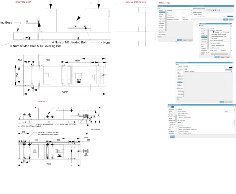
Thanks for your attention, I am seeking some advise as after export there is unknown center line on the M8 Bolt.

I tried to change the hidden line to 0.13

Below the file link of the issue and my setting [Better resolution]
Link
Centre_line_bolt_oversized_width_qupu81.jpg


Thanks you for your kind time and attention
 
Replies continue below

Recommended for you

It is probably a point.
I do not remember if there is a way to adjust the point size on a drawing in NX12.
Somebody probably thought it was a good idea to put a point in the model for constraining but it only complicates things.

Jerry J.
UGV5-NX1884
 
Hi Thanks for your inputs,

shall i trace this from my 3d model constraints.

the point get enlarged due to the visible line selected at 0.01 mm where point is default.

anyway to chanhe point line size here ?. wjat is the best way to get rid this.
 
Hi Jerry,

The problem is the point right. I tried to change this setting, is still can not work, every point of hole and bolt has about 4 of this, i need to right click and show all the drafting line (Extracted edges)and hide one by one, it is quite a tedious process, anyway if any more practical way to turn this off would be great.


Is there an object of the type "Point" in the fastener ?
Press "Ctrl+I" (= Information -Object) and select "that object", the que line will report the type.
also , the listing will tell the type.

If this is a point, you should , if that fastener is defined as "expected" , be able to replace the reference set of the fasteners ( all of them ) to "model" and the point should disappear.

If the point is included in the model reference set, you might want to move all points to a hidden layer in the drawing file.
If you select the "move to layer" and then set selection filter to "point" you should be able to select all by "Select all".

Regards,
Tomas

Never try to teach a pig to sing. I wastes your time and it annoys the pig.:)
 
I was thinking about one of the things that Toost just wrote above.
If the points are in the MODEL reference set then take them out of it.
When you do the assembly constraining, and want to utilize the points, then use the ENTIRE PART reference set of the nuts and the points will be there, then change the reference set to MODEL when the constraining is complete.

Jerry J.
UGV5-NX1884
 
Status
Not open for further replies.

Part and Inventory Search

Sponsor