Hi there,
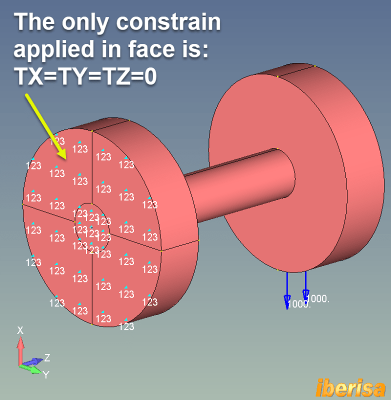
I have a problem for a couple of days on NX12 Simulation, using NASTRAN solver. I am unable to lock rotation of a face while applying displacement or force over one axis. Whether I use "user-defined constraint" or "fix all rotations", on the face I want to constraint, it just won't. My model is similar to a tube with two flanges, one at each side. Here is a draft of the simulation :
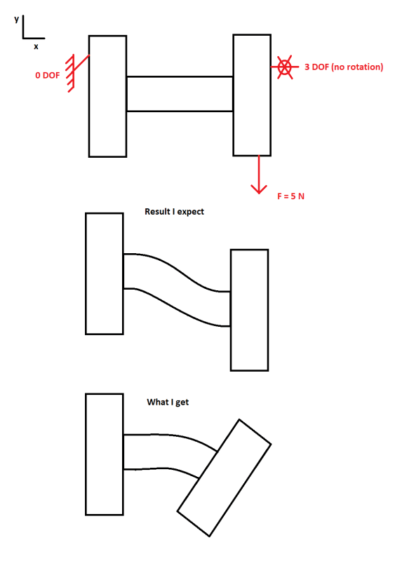
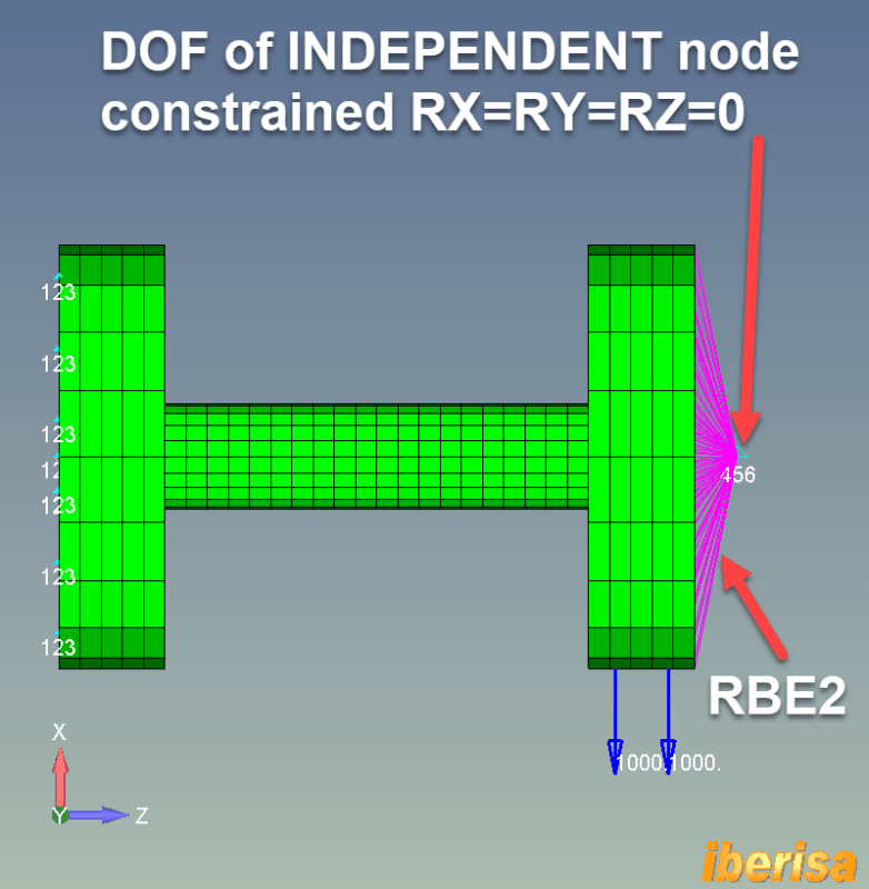
It is like NX is considering rotation lock at element local CSYS level.
I do get what I expect using a slider constraint (along Y), but slider also lock X which I don't want to be lock. I tried a bunch of solution, bc, but it always behave the same.
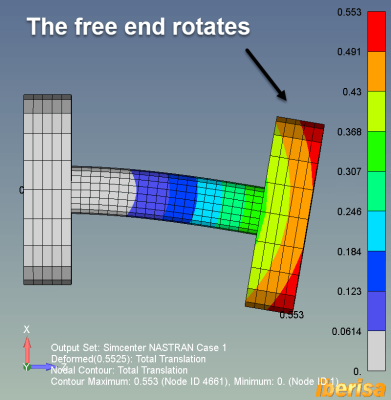
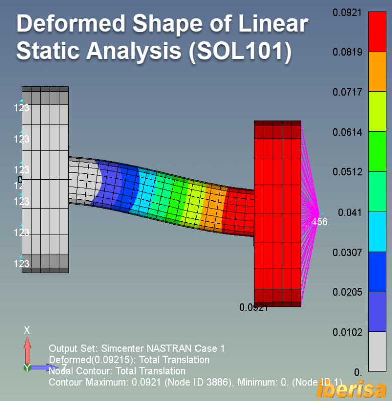
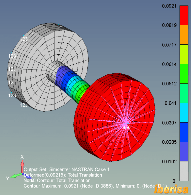
When I look to results, I do have a gradient of x displacement on the loaded face, but if I plot rotation around z, I have 0 on the entire model. How is that even possible ?
I have a problem for a couple of days on NX12 Simulation, using NASTRAN solver. I am unable to lock rotation of a face while applying displacement or force over one axis. Whether I use "user-defined constraint" or "fix all rotations", on the face I want to constraint, it just won't. My model is similar to a tube with two flanges, one at each side. Here is a draft of the simulation :
It is like NX is considering rotation lock at element local CSYS level.
I do get what I expect using a slider constraint (along Y), but slider also lock X which I don't want to be lock. I tried a bunch of solution, bc, but it always behave the same.
When I look to results, I do have a gradient of x displacement on the loaded face, but if I plot rotation around z, I have 0 on the entire model. How is that even possible ?