Hello,
I'm trying to mill a groove wrapped around a 4th axis.
This groove has a variable width and isn't straight.
I first want to use a flat endmill with diameter 1mm to try and cut as much as possible (the minimum width is less than 1mm).
For this I want(ed) to use "Variable Streamline" with drive method "Streamline" and Tool Axis "Away from Line".
I have selected the bottom surface of the groove as Cut Area and the adjecent curves as Flow Curves (no Cross Curves).
For drive settings I have chosen Tool Position "On" as "Tanto" resulted in a strange tool path where the tool jumps up and down.
For cut pattern I have chosen "Helical or Spiral".
The stepover is set to "Constant" with a Maximum Distance of 60% of the tool diameter.
At Cutting Parameters, at the More tab, I have set Max (Cut) Step to 60% of the tool diameter.
What is the difference between these?
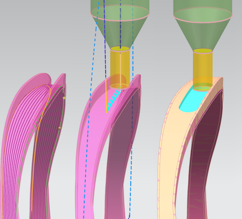
A preview of the drive method streamlines shows plenty of lines.
But when I generate the path, only a small part appears to be milled.
The 3D IPW clearly shows there is more material that can be cut.
Does someone know why the tool path doesn't go further?
And does anyone know why it doesn't step over to the other side?
Kind regards,
Jeroen Duré
I'm trying to mill a groove wrapped around a 4th axis.
This groove has a variable width and isn't straight.
I first want to use a flat endmill with diameter 1mm to try and cut as much as possible (the minimum width is less than 1mm).
For this I want(ed) to use "Variable Streamline" with drive method "Streamline" and Tool Axis "Away from Line".
I have selected the bottom surface of the groove as Cut Area and the adjecent curves as Flow Curves (no Cross Curves).
For drive settings I have chosen Tool Position "On" as "Tanto" resulted in a strange tool path where the tool jumps up and down.
For cut pattern I have chosen "Helical or Spiral".
The stepover is set to "Constant" with a Maximum Distance of 60% of the tool diameter.
At Cutting Parameters, at the More tab, I have set Max (Cut) Step to 60% of the tool diameter.
What is the difference between these?
A preview of the drive method streamlines shows plenty of lines.
But when I generate the path, only a small part appears to be milled.
The 3D IPW clearly shows there is more material that can be cut.
Does someone know why the tool path doesn't go further?
And does anyone know why it doesn't step over to the other side?
Kind regards,
Jeroen Duré