NXerGeneration
Automotive
Hello,
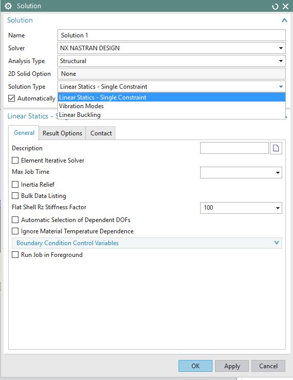
In my quest to learn NX10 Design Simulation, I have run into the following situation.
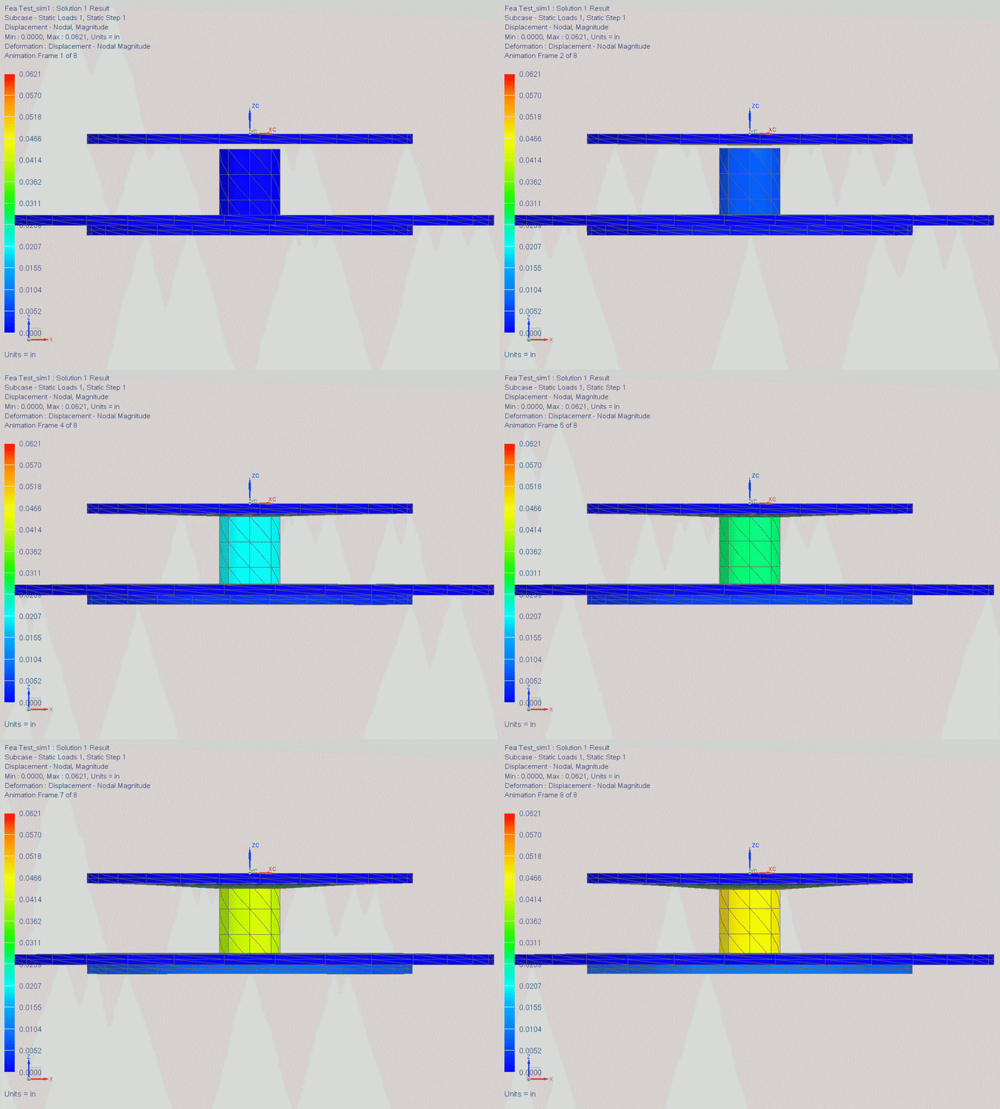
I'm not sure how to set the Deformation representation to show the true Displacement result. Is Scale of 1.00 for % Model the proper setting?
Also based on the attached, its a simple load case where forces are applied to simulate a clamping condition, there is small gap between the Yellow and Blue component, however in its Displacement solution, there seems to be collision between the two, this brings me to my initial Deformation representation question or is something else set up incorrectly?
See links to the attached images


