Continue to Site

Eng-Tips is the largest engineering community on the Internet

Intelligent Work Forums for Engineering Professionals

  • Congratulations KootK on being selected by the Eng-Tips community for having the most helpful posts in the forums last week. Way to Go!

NX11 Flange (SHEET METAL FEATURE)? 3

Status
Not open for further replies.

Kenja824

Automotive
Nov 5, 2014
949
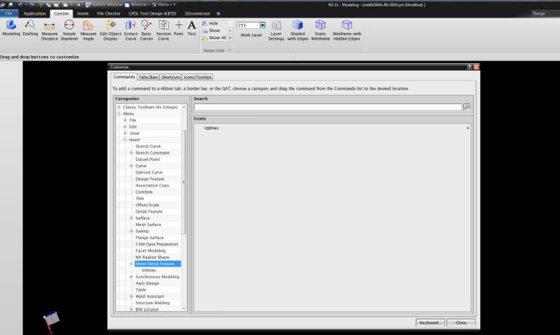
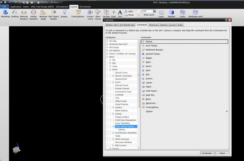
In NX9, when in modeling, we could go to Insert - Sheet Metal Feature - Flange

There was also a different flange option in sheet metal application but this one was available in modeling.

This one would allow you to select an edge of a face, and fill in the Infer Width(which was grayed out at 100 because it would use the entire surface length), Tangent Length, Bend Angle, and inside radius. It would then extend the face out, bending it to the angle you put in, and extend the surface flat again for the length you placed in it.

Is this feature still available in NX11 anywhere? I cant seem to find it.

If not, is there any code out there to make a flange simple?
 
Replies continue below

Recommended for you

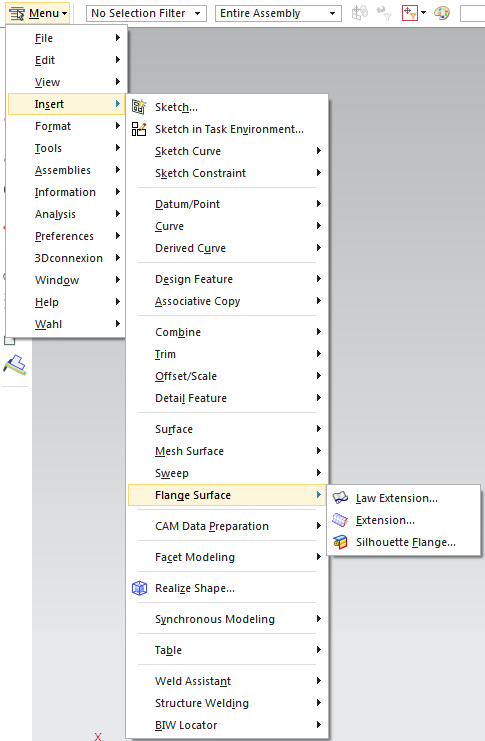
I'm running NX 9 and I don't see any "sheet metal feature" available on the modeling application insert menu; perhaps it was a customized menu? However, there are a few options in the "flange surface" menu...

flange_surface_krwuac.png


www.nxjournaling.com
 
Hi Kenja,

starting with NX 3 SPLM introduced a new module called "NX Sheet Metal". The old in Modeling was called "Sheet Metal Design". Both modules existed in parallel for a while. In NX 9 (or 8.5) you had to set an environment variable that Sheet Metal Design was available. In NX 12 this is finally over. The approach and design in NX Sheet Metal differs a lot from Sheet Metal Design. In the meantime the new module is pretty good.
Hope this explains also the Forming/Flattening question in the other thread.

Thomas
 
This is funny to me because I just finished leaving a new post asking of a new way to make a flange and then saw this one replied to. lol

You said in NX12 it is changed, but is it still just an environmental variable for NX11?

Thanks for this info BTW. I really appreciate it. Today is the first day for everyone to be switched to NX11 and I already have had 2 people ask about this.
 
Hey Thomas

I have been looking at the variables and such. Would you know what variable it is and where it needs to be pathed to? If that makes sense. The IT person told me to ask this. :)

Though in NX( what we had was called "Flange" and was in a directory INSERT -> SHEET METAL FEATURE.

The closest flange I have found is the one that is in the Sheet Metal application. When I open it, this looks like it has the same info for it, but this doesnt seem to work on solid bodies, as it will not allow us to select any edges of our bodies.
 
I would encourage all sheet metal users to use the NX Sheet Metal application - it covers 99.9% of all the functionality available in the now unsupported Modeling Sheet Metal Design commands that were retired in NX7.5. The functions were made available under env var for a few releases while the new sheet metal application was introduced. Now, from NX11, that use is restricted.

If something is not there and you are left without a function from NX11, then contact GTAC. They will pass on the issue to the development team who are pro-active in ensuring the legacy features are covered. If users continue with the old function then Siemens has no way to respond to missing functions.

Kenja824 said:
The closest flange I have found is the one that is in the Sheet Metal application. When I open it, this looks like it has the same info for it, but this doesnt seem to work on solid bodies, as it will not allow us to select any edges of our bodies.

To use sheet metal features, the part needs to be created in the applcation use a base feature or converted using Convert to Sheet Metal. I would advise some training.
 
deedub777 said:
To use sheet metal features, the part needs to be created in the application use a base feature or converted using Convert to Sheet Metal. I would advise some training.

What do we do when everything we make is in solid bodies in modeling and we need to make a 6mm thick bent switch bracket that has two bends at different angles? "Flange" sounds like something you would only use with sheet bodies, but that modeling feature of it was a great help when working in modeling. I have had no less than 5 guys come asking what happened to it.

If there is an easy way to make a bent bracket that NX has available that the Flange feature in modeling is not needed, I know several designers who would like to know right now.
 
Hi Kenja,

forget it to try the "old" Sheet Metal. I don't know how official setting is or was. If you are really eager to know it, ask GTAC.
I agree totally with deedub777: Use the new Sheet Metal! If you have a Solid Body created in Modelling and you want to use it in Sheet Metal, switch the application to Sheet Metal and add a "Convert to Sheet Metal". Condition for a successful convert is, that the part meets some condition - should at least look like a sheet metal part. If the convert is successfully you can continue with the Sheet Metal commands. But I recommend from begin on to design the part with Sheet Metal commands.

Thomas
 
In playing with it, it looks like the new way does work by using the tab feature first. I showed a designer and he says it looks like it will do the trick once they get used to it. Personally I think I may put this to GTAC still though. The old feature was so simple for everyone. Though this one will work better than nothing, I find it sort of ridiculous that we should have to switch applications to design a specific detail and then the new one still isnt as simple as the old.

Part of me is still hoping the old feature may have been something the customer had given us at one point in a tool kit or something, as I have gotten the idea others dont quite know the feature I am talking about. But in the end, if worse comes to worse and we have to switch applications just to make one specific detail when we make them, then still not horrible. Just harder because we have gotten spoiled and I always struggle with the idea when any company would change things to make them more difficult rather than better. I struggle with things that lack logic and sense to me. lol
 
If you are designing a sheet metal part, why not design the entire part using the dedicated sheet metal application? There are plenty of tutorials on the Siemens learning center and once proficient you would see the power and versatility of the application that feeds into the manufacturing process. If and when you put in a request to GTAC, be sure to upload some sample parts so the development team at Siemens can review and suggest the most appropriate methods for you.
Remember, the old SMD functions are no longer supported and if you got into trouble, you have no support.
 
I think that is what the confusion is, so I will try to explain better.

We dont design anything sheet metal. We design tools/fixtures for clamping and welding the sheet bodies together. Quite often in designing fixtures, we need to design a bent bracket that might be bent at any angle in two places. I am attaching a picture of one I just created for this purpose. Keep in mind this one is a basic one and crudely put together without focusing on getting all the distances right for any purpose. The angles are not always 90° and often they may extend out to the side as well.

In modeling this up, I had to make a block. I added a pocket to one side at the end and added another pocket to the other side at the other end. I then had to put blends to the corners. It didnt take long but it took too long but when you are used to the old Flange feature in Modeling, it takes way too long. The new Sheet Metal flange is faster than manually making it but not as fast as the old flange in modeling.

As it looks like we are stuck with this change, we will just have to accept the new way of doing it. Our biggest worry however is that there will soon come a point when we will run into a problem we are not expecting with using sheet bodies instead of solid bodies. I checked and we can move faces and place chamfers and such on the new flange. I added a stock size and that ran well with our stocklist program. So far it all looks good enough to work with. But I have not tried everything yet and there is that fear that we will find that using a sheet body instead of a solid body will cause us some headache somewhere along the way that we just havent thought of yet. One designer asked if these will pass file checker okay. I have yet to try this. I dont believe it will be a problem. Hopefully not.

We dont use sheet bodies for anything else and never had to for these. Now that changes and a lot of the designers are unhappy with this change. Dont get me wrong, I am not trying to continue to complain or anything. I am just trying to explain why this is an issue from our point of view. And I am just looking to find the best way to make everyone here happy. Its not just being unhappy with something that changed and isnt any more difficult. In this case, the new way is more difficult for us, and we are not comfortable yet that no other problems will arise from it because we dont usually use sheet bodies.
 
 http://files.engineering.com/getfile.aspx?folder=b2854148-068d-4f32-bffa-0de2f70c49ba&file=bracket.JPG
Sorry Kenja, please take a look into tutorials, youtube, whatever and inform yourself about NX Sheet Metal. Sheet Metal parts are NOT Sheet Bodies, they are Solid Bodies too...
About the old Sheet Metal: I created some weeks ago in NX 6 a simple Sheet Metal part with the old commands (for test purpose) and I cried. I doubt that you are faster in (pure) Modeling or old SMD to create this bracket than somebody who knows how to use the new NX Sheet Metal. And Sheet Metal takes automatically care about the sheet metal conditions (eg. continuous thickness).
 
Hi @Kenja824,
Thanks for taking the time to explain.

You mention blocks and pockets so pretty sure you have been using NX for a long time. NX has moved on and I'm sure the new methods would bring you better productivity and ease of use once you have learnt them? I know you mentioned your users do not like sketch however take a look at the contour flange command, you can create your simple bracket profile in one feature driven by a sketch. Take a look at the attached movie.

I also suggest you sign up to the Siemens NX Design Community where there's a wealth of information and also a specific sheet metal users group.
 
 http://files.engineering.com/getfile.aspx?folder=5a0b2ba5-e778-4337-a246-edd6d955a50a&file=SimpleBracket.mp4
I do appreciate the help.

Thomas, I can assure you the old feature we had in NX9 was indeed quicker for us but that is because we do all of our work from modeling. I think you must do most of your work from sheet metal so this is fastest for you. You would not like it if NX took your flange program away from you and made you move to modeling to make your flanges. I really dont think either flange is faster overall. It just depends on where you do most of your work. You can just hit the flange button and make your flange. We cant do that. We need to switch applications and then make a sketch or hit the tab button to connect to our solid bodies first. This is a case where the speed is all perspective. Still, I do appreciate the time you have spent in helping. I think now I need to stop worrying about modeling and sheet metal and just focus on the fastest way to do things for my company from here out. lol

Deedub, I will check that out. I cannot believe it will ever be as easy as it was for us, but that is in the past now anyway. So now I need to learn the fastest way for making these that I can now days. Thanks.
 
Status
Not open for further replies.

Part and Inventory Search

Sponsor