Continue to Site

Eng-Tips is the largest engineering community on the Internet

Intelligent Work Forums for Engineering Professionals

  • Congratulations cowski on being selected by the Eng-Tips community for having the most helpful posts in the forums last week. Way to Go!

NX9 Bounding Box function 6

Status
Not open for further replies.

Arkance/PhoeNX

Mechanical
Mar 2, 2010
869
Seen posts here and had customers ask about bounding box functionality in NX.
The answer was to use Journals/NX Open/Grip etc to solve the problem.

NX has a function called Create Box that existed in the Wizards (Mold, Die or Electrode).
Without one of those Wizard licenses, you couldn't use it.

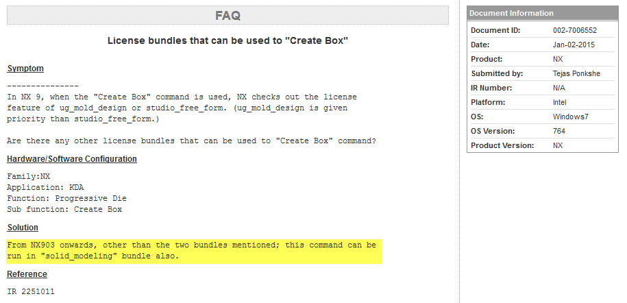
Saw an IR recently (see image below) which says that from NX9.0.3 onwards, you only need a solid modeling license to use the function.

download.aspx


Thought it was pretty neat function so we've made a video to show how to access it and how it works: Also did some testing and NX9.0.2 can also do the same.
NX10 version of Create Box is better as well.


Anthony Galante
Senior Support Engineer


NX3 to NX10 with almost every MR (21versions)
 
Replies continue below

Recommended for you

Is there any way of getting the dimensions of the solid belonging to create box? there seems to be no attributes or expressions associated with it, and the knowledge fusion class used to create the feature shows only the inputs points, vectors, and hostpointers but not the output. Thus I suspect that the only way to get the length x width x height of the bounding box is to actually create associative measures or PMI dimensions?
 
@petulf, no way that I could see. There is another function that works very similar to Create Box but you need a wizard license. It reports on the dialog the 3 dimensions and creates an attribute with an a value like 300 x 340 x 356.

@phillpd, NX9 or NX10? I ask because in my playing with it I've seen no errors in NX9 but I did get an error in NX10, not the same as yours though.

Anthony Galante
Senior Support Engineer


NX3 to NX10 with almost every MR (21versions)
 
Maybe someone could help me with this, petulf is trying to do something that I have been somewhat doing

What I do sometimes is create the box, then create 3 associative dimensions and call them sz1, sz2 and sz3

Now I have 3 expressions that I can use that will automatically update

On my drawing I can use <X.4@sz1> X <X.4@sz2> X <X.4@sz3> to show the sizes

But is there any way to get these to an attribute so they show up on my bom in the format sz1 X sx2 X sz3 (I do not want 3 columns in my BOM)

Thanks


Brian Marchand-Die Designer
NX 9.0.2.5 / PDW
Dell Precision T7610 w/Xeon ES-2609
16G Ram - Nvidia Quadro K5000
Win 7 Pro x64
 
Anthony, I'm running NX9.0.3.4 MP03.

It does work in NX10

NX 9.0.3.4
NX 10 (Testing)
Windows 7 64 (Windows 8.1 Tablet)
 
When I use command finder, I do not see Mold box or Create box
any suggestions? I currently use a journal from Cohens NXcustom setup to make a bounding box, but i'm interested in an actual command
 
Robnewcomb:
Do you run 902 or later ?
As Anthony noted in the first post, its in 902 and later.

Regards,
Tomas
 
PhoeNX: Yes mold wizard has the stock size tool but it is not associative, it only runs the bounding box function and then as you say stores the result into two attribute strings but it will not update if the underlying objects are changed.

phillipd: Create box uses knowledge fusion functions so i would start troubleshooting there, i run the same version and it works.

bmarchand: You could create an expression that concatenates the expressions using the stringvalue() function, the following example uses referenced attributes but measurement expressions will work the same way.

bRi3FAY.png


We currently use our own NXOpen program to get a complete list of stocksizes as we find the current NX bounding box tools to be lacking. This solution is not optimal as the values are not associative thus we do not want to push them directly into drawings and teamcenter.

What I would like to see in an NX bounding box feature
[ul]
[li]Be contained in one fully associative feature.
[li]Outputs the bounding box dimensions into attributes and or expressions, so that the values can be used downstream in drafting and teamcenter.[/li]
[li]Can reference abs, wcs or a datum csys feature as the bounding box frame reference.[/li]
[li]Optional creation of solid, i.e. so that it is only visible from within the feature dialog.[/li]
[/li]
[/ul]

Our current plan is to create a knowledge fusion feature for this, but it would be oh so much better to be able to do this with native NX feature modeling.
 
I am running 9.0.3.4 MP2

heres the journal i run

Code:
Option Strict Off

Imports System

Imports NXOpen
Imports NXOpen.UI
Imports NXOpen.Utilities
Imports NXOpen.UF

Module make_bounding_block_of_selected_body_relative_to_wcs

    Dim s As Session = Session.GetSession()
    Dim ufs As UFSession = UFSession.GetUFSession()
    Dim lw As ListingWindow = s.ListingWindow()

    Sub Main()

        Dim a_body As NXOpen.Tag = NXOpen.Tag.Null
        Dim csys As NXOpen.Tag = NXOpen.Tag.Null
        Dim target As NXOpen.Tag = NXOpen.Tag.Null
        Dim blockFeature As NXOpen.Tag = NXOpen.Tag.Null

        Dim min_corner(2) As Double
        Dim directions(2, 2) As Double
        Dim distances(2) As Double
        Dim edge_len(2) As String

        While select_a_body(a_body) = Selection.Response.Ok

            ufs.Csys.AskWcs(csys)

            ufs.Modl.AskBoundingBoxExact(a_body, csys, min_corner, directions, _
                distances)

            lw.Open()

            lw.WriteLine("Min_corner: " & _
                min_corner(0).ToString & ", " & _
                min_corner(1).ToString & ", " & _
                min_corner(2).ToString & ", ")

            lw.WriteLine("X direction: " & _
                directions(0, 0).ToString & ", " & _
                directions(0, 1).ToString & ", " & _
                directions(0, 2).ToString & ", ")
            lw.WriteLine("X distance: " & _
                distances(0).ToString)

            lw.WriteLine("Y direction: " & _
                directions(1, 0).ToString & ", " & _
                directions(1, 1).ToString & ", " & _
                directions(1, 2).ToString & ", ")
            lw.WriteLine("Y distance: " & _
                distances(1).ToString)

            lw.WriteLine("Z direction: " & _
                directions(2, 0).ToString & ", " & _
                directions(2, 1).ToString & ", " & _
                directions(2, 2).ToString & ", ")
            lw.WriteLine("Z distance: " & _
                distances(2).ToString)

            edge_len(0) = distances(0).ToString()
            edge_len(1) = distances(1).ToString()
            edge_len(2) = distances(2).ToString()

            ufs.Modl.CreateBlock(FeatureSigns.Nullsign, _
                                 target, min_corner, edge_len, blockFeature)
        End While

    End Sub

    Function select_a_body(ByRef a_body As NXOpen.Tag) As Selection.Response

        Dim message As String = "Select a body"
        Dim title As String = "Select a body"
        Dim scope As Integer = UFConstants.UF_UI_SEL_SCOPE_ANY_IN_ASSEMBLY
        Dim response As Integer

        Dim view As NXOpen.Tag
        Dim cursor(2) As Double
        Dim ip As UFUi.SelInitFnT = AddressOf body_init_proc

        ufs.Ui.LockUgAccess(UFConstants.UF_UI_FROM_CUSTOM)

        Try
            ufs.Ui.SelectWithSingleDialog(message, title, scope, ip, _
                         Nothing, response, a_body, cursor, view)
        Finally
            ufs.Ui.UnlockUgAccess(UFConstants.UF_UI_FROM_CUSTOM)
        End Try

        If response <> UFConstants.UF_UI_OBJECT_SELECTED And _
           response <> UFConstants.UF_UI_OBJECT_SELECTED_BY_NAME Then
            Return Selection.Response.Cancel
        Else
            ufs.Disp.SetHighlight(a_body, 0)
            Return Selection.Response.Ok
        End If

    End Function

    Function body_init_proc(ByVal select_ As IntPtr, _
                           ByVal userdata As IntPtr) As Integer

        Dim num_triples As Integer = 1
        Dim mask_triples(0) As UFUi.Mask
        mask_triples(0).object_type = UFConstants.UF_solid_type
        mask_triples(0).object_subtype = UFConstants.UF_solid_body_subtype
        mask_triples(0).solid_type = UFConstants.UF_UI_SEL_FEATURE_BODY

        ufs.Ui.SetSelMask(select_, _
                           UFUi.SelMaskAction.SelMaskClearAndEnableSpecific, _
                           num_triples, mask_triples)
        Return UFConstants.UF_UI_SEL_SUCCESS

    End Function

    Public Function GetUnloadOption(ByVal dummy As String) As Integer

        GetUnloadOption = UFConstants.UF_UNLOAD_IMMEDIATELY

    End Function

End Module
 
petulf, could you show aw an example--I tried the function but cannot get it to accept a 3 expressions in same stringfunction

Brian Marchand-Die Designer
NX 9.0.2.5 / PDW
Dell Precision T7610 w/Xeon ES-2609
16G Ram - Nvidia Quadro K5000
Win 7 Pro x64
 
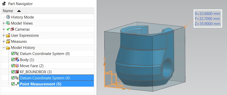
Another technique for associatively collecting the three dimensions of the bounding box would be to put an associative Datum CSYS on one corner of the bounding box and then create an associative Point Measurement [also new in NX 9] on the opposite corner of the block, RELATIVE to the Datum CSYS. This will give you an accurate set of dimensions for the box, regardless of orientation or size changes:

getfile.aspx


getfile.aspx


...and with the Point Measurement feature, you can choose whether to get just one "Point" expression for the answer, or optionally create all three components dimensions as individual "Number" expressions as well:

getfile.aspx


Just another thought. :)

Taylor Anderson
NX Product Manager, Knowledge Reuse and NX Design
Product Engineering Software
Siemens Product Lifecycle Management Software Inc.
(Phoenix, Arizona)
 
Let me try again with those images...

point_meas_1.jpg


point_meas_2.jpg


point_meas_exp.jpg


Taylor Anderson
NX Product Manager, Knowledge Reuse and NX Design
Product Engineering Software
Siemens Product Lifecycle Management Software Inc.
(Phoenix, Arizona)
 
petulf: I suspect you could get awfully close to your desired end state with a UDF -- particularly using the NX 10 version of the bounding box -- and with the technique I showed.

(Target body and orientation CSYS selections as two inputs,
extract faces as input for bounding box,
create Bounding Box feature,
create Datum CSYS feature,
create Point Measurement,
which creates expressions...)

...and avoiding the ongoing maintenance of a programmatic solution would probably be worth the tradeoffs. :)

Taylor Anderson
NX Product Manager, Knowledge Reuse and NX Design
Product Engineering Software
Siemens Product Lifecycle Management Software Inc.
(Phoenix, Arizona)
 
@robnewcomb, make sure you're in modeling when using command finder.
Otherwise, the attached ribbon bar file will add a ribbon tab with the right Create Box function.

To automatically load a RTB file at NX startup, put it in the startup folder pointed to via the USER,GROUP or SITE DIR variables.

I made a video showing how I would do that for the USER variable UGII_USER_DIR.

RTB File

Video file


Anthony Galante
Senior Support Engineer


NX3 to NX10 with almost every MR (21versions)
 
TaylorAnderson

That is a great Idea

How would I get the values to a single attribute so I can add a column to my bom and have "value X value X value"

petulf suggested stringvalue() but I haven't figured out how yet

Thanks

Brian Marchand-Die Designer
NX 9.0.2.5 / PDW
Dell Precision T7610 w/Xeon ES-2609
16G Ram - Nvidia Quadro K5000
Win 7 Pro x64
 
Taylor: Good idea and had completely missed the point measurement feature which is sure to come in handy. To bad that create box reference csys is not associative and the object selection does not use selection rules as input but directly references the object tags. Thus it is not possible to create an associative udf (extract feature face will not help) that takes a body and csys feature as input. An improvement request for the create box feature might be in order?

I have included a test part that tries to create what we want with out of the box features, the non-associative nature of create box is the only obstacle.
oIfnDGD.png


bmarchand: Check out the included nx9 part for an example of how to convert numbers to strings.
 
 http://files.engineering.com/getfile.aspx?folder=7b09dd3a-52a0-4d88-b073-b0237aefc195&file=ootb_bounding_box_measurement_example.prt
petulf,
I think most of what you want may already exist (as a custom, freely available solution from GTAC). Search the GTAC solution center for nx_api3871 (VB version) or nx_api4910 (C# version).

Amy Webster said:
This application implements a new feature type called Bounding Box. This
wireframe feature is made up of 12 lines which correspond to the edges of the
smallest box which will contain all of the selected geometry. The box is
oriented with respect to a selected coordinate system. This box is associative
and will change size as the contents are modified.

The geometry to be contained in the box and the orientation of the box can be
changed at any time by editting the feature.

If you want an associative solid block for a machining blank for example, just
create one by selecting diagonal corners of the wireframe box. This
application does not do this because a UDO Feature cannot link to or own a
solid body or feature. See PR 1798592.

This application must be run as a dll. An NX Open .NET Author or NX Open
Toolkits Author license is required. Tools-> Journal-> Play will only work
once. Put the boundingBox.dll in any "startup" folder, e.g.
UGII_USER_DIR\startup. Put the boundingBox.dlx in any "application" folder,
e.g. UGII_USER_DIR\application.

www.nxjournaling.com
 
Brian:

So, after making sure I was using a string expression, Stringvalue() worked for me when I set it up like this:

[pre]stringvalue(p17) + " x " + stringvalue(p18) + " x " + stringvalue(p19)[/pre]

...but it doesn't give me control over the number of decimals displayed. For my oblique bounding box, this resulted in a string something like:

[pre]42.208055775 x 33.351831883 x 41.032078484[/pre]

...and that may be less than desirable. :)

Using the format() function like this:

[pre]format("%0.1f",p17 ) + " x " + format("%0.1f",p18 ) + " x " + format("%0.1f",p19 )[/pre]

...gave me control over the number of decimal places displayed, for a result more like this:

[pre]42.2 x 33.4 x 41.0[/pre]

Once you've got the string attribute sorted out, then go over into the Part Attributes dialog, and pull the expression value into a string attribute with the "Link to Expression" button:

150108_attr_link1.jpg


Once you've selected your string expression and pushed Apply or OK, the selected expression and the value should be visible over there, too:

150108_attr_link2.jpg


(...and the "Link to Expression" button will switch to a "Break Expression Link" button.)

Make sense? Does that help?

Taylor Anderson
NX Product Manager, Knowledge Reuse and NX Design
Product Engineering Software
Siemens Product Lifecycle Management Software Inc.
(Phoenix, Arizona)
 
Status
Not open for further replies.

Part and Inventory Search

Sponsor