Continue to Site

Eng-Tips is the largest engineering community on the Internet

Intelligent Work Forums for Engineering Professionals

  • Congratulations cowski on being selected by the Eng-Tips community for having the most helpful posts in the forums last week. Way to Go!

NXOpen Section view creation

Husky Dusky

Mechanical
Mar 12, 2025
5
Hello,

Being a newbie with NX programming and customization need some help here.

I'm trying to create a section view from a drawing and with help of Journal have the basic code. I'm trying to make it generic so that it can be run for any drawing in future.

I'm trying to replace the FindObject method from Journal code to User selection prompt but it doesnt allow us to select the drafting spline from the view.

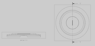
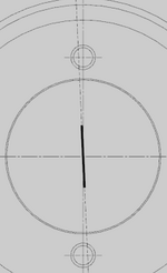
Here is the code that I have currently. The extracted edge from the view (left view) looks like this

(Extracted Edge) EDGE * 120 REVOLVED(7) 11069 {(26,-61.9711424777695,-159)(11.8650408521507,0.1576547870641,-159)(26,61.9711424777695,-159) REVOLVED(7)},


And its Type = 9 and subtype= 0 (got this by using AskTypeAndSubtype method on the displayable object from the view).


I'm using the same filter on the UI prompt as

Code:
NXOpen.Selection.MaskTriple[] mask = new NXOpen.Selection.MaskTriple[1];
mask[0].Type = 9;
mask[0].Subtype = 0;


Selection.Response response = theUI.SelectionManager.SelectTaggedObject("Select a curve", "Select a curve", NXOpen.Selection.SelectionScope.AnyInAssembly, NXOpen.Selection.SelectionAction.ClearAndEnableSpecific, true, true, mask, out selectedObjects, out cursor);

But the curve is NOT selectable. Any help is appreciated.

Thanks.
 
Replies continue below

Recommended for you

I suspect that you might need to use .SetCursorView to allow selection from within a drafting view.
Code:
theUFSession.Ui.SetCursorView(0)
Substitute your UFSession variable for "theUFSession" above. Add this line of code right before the call to .SelectTaggedObject.
 
I suspect that you might need to use .SetCursorView to allow selection from within a drafting view.
Code:
theUFSession.Ui.SetCursorView(0)
Substitute your UFSession variable for "theUFSession" above. Add this line of code right before the call to .SelectTaggedObject.
Hi @cowski,

With your suggestion now we are able to select the curve and with the Journal code able to get the section view however the view 90 deg rotated.

Our left view is based on co-ordinates Y and Z and we are using select screen Position method to get the location for the section view from the user.

response = theUI.SelectionManager.SelectScreenPosition("Select the section view location", out View, out loc);

But the co-ordinates we received from the above method is of screen position XYZ and our origin (0,0,0) is the center of the left view.

Any pointers on how we can get this right?

Thanks!
 
Last edited:
I don't entirely understand the issue from your short description, but it sounds like you want to select a drafting curve with .SelectTaggedObject, then select a location on the drawing sheet itself with .SelectScreenPosition in the same journal. If so, be sure to use .SetCursorView(1) before the SelectScreenPosition call to limit selection to the work view, which is usually the drawing sheet itself (you may need to check/change the current work view in code).

If you are selecting a point in the model and want to know the location on the drawing sheet, you can use .MapModelToDrawing. Use .MapDrawingToModel to go the other way.
 
Sorry if I was not clear earlier and Yes your understanding is correct. To give you a background we are generating left and section view for a model. We created a journal for the same and currently trying to replicate the functionality in NX open through windows form submit as need to collect few other details from the user. Once the left view is created on form submit we are prompting user for the section view selection and the position for the section view on the drawing sheet. Section view is created however is rotated 90 deg. We are using cursor point3d value from the .SelectTaggedObject method for the selected drafting curve as our section line path and the point3d value from .SelectScreenPosition method as location for our section view.

The issue is section view generated is 90 deg rotated, the cursor point3d value from .SelectTaggedObject has value from origin which is center of our left view however .SelectScreenPosition has point3d value which is way different (or way above) from cursor point3d value.

Attaching image for reference.

I don't entirely understand the issue from your short description, but it sounds like you want to select a drafting curve with .SelectTaggedObject, then select a location on the drawing sheet itself with .SelectScreenPosition in the same journal. If so, be sure to use .SetCursorView(1) before the SelectScreenPosition call to limit selection to the work view, which is usually the drawing sheet itself (you may need to check/change the current work view in code).

If you are selecting a point in the model and want to know the location on the drawing sheet, you can use .MapModelToDrawing. Use .MapDrawingToModel to go the other way.
 

Attachments

  • Screenshot.png
    Screenshot.png
    32.9 KB · Views: 4
Last edited:
Hi @cowski,

Can you help with this? I'm trying to create a section view using NXOPEN api when I select a circle through UI selection manager the section line is NOT passing through the center of the circle. Currently I select 3 different circle through which I want the section line pass through all its center but it connects through only one center as shown. How do I make it to pass through center of all selected circle?

Any help is appreciated.

Thanks
 

Attachments

  • Screenshot 2025-03-30 235040.png
    Screenshot 2025-03-30 235040.png
    20.2 KB · Views: 3

Part and Inventory Search

Sponsor