Eng-Tips is the largest engineering community on the Internet

Intelligent Work Forums for Engineering Professionals

  • Congratulations waross on being selected by the Tek-Tips community for having the most helpful posts in the forums last week. Way to Go!

Obtaining mode shapes from velocity FRF

Status
Not open for further replies.

enterprixe

Aerospace
Dec 4, 2017
9
0
0
ES
Hello,

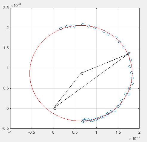
Recently i have been tasked to do the modal analysis of the data collected from a test. I was able to obtain its natural frequencies, damping coefficients(viscous and structural) and the modal constant using a SDOF descomposition of the FRF. I am supposed to obtain 4 mode shapes ( since i focus on 4 natural frequencies ) but i have not seen it explained well in any of the references i have looked up to. I know it has something to do with the imaginary part of the FRF but i can't get the complex mode shapes to progress any further in my work.

Help with be appreciated, Thank you.
 
Replies continue below

Recommended for you

The complex mode shape is an amplitude and phase at each response point, for each resonant frequency. In a lightly damped system it may be acceptable to merely use the imaginary component of each FRF at the resonant frequency. That's not very good practice in general but it does work on simple systems.

Otherwise refer to this


Cheers

Greg Locock


New here? Try reading these, they might help FAQ731-376
 
But i was wondering if there is any good document that explains step by step what you need to take to reconstruct the mode shapes. Because in many sites its explained in a way that does not give insight of how you should program it in something like MATLAB and i dont really know what to do in this step.
 
It is only possible it reconconstruct the mode shapes under rather severe constraints: linearity, minimum phase response, and more pactically, only for rather simple systems in which you do not have closely spaced moding (degenerate modes). You'll have to grab your texts and get to work, there are no easy answers in 240 characters or less so to say...
 
Okey so i managed to get some achievements on this. I extract the modal parameter, which is the product of 2 elements of the modal matrix, and knowing whats my driving point i manage to reescalate all the other mode shapes elements. The problem im having now is that, for viscous damping, these modes should be complex, but doing this process with the FRF modulus i only get a modulus (as expected). I do not know where should i look to add the phase to these mode shapes and get the complex mode shapes for viscous damping.

Thank you in advance.
 
The damping of each mode is a global property of the mode. You can estimate it by looking at one of your FRFs that shows the peak clearly, and use the half power method, or you can attempt to synthesise an FRF using assumed damping (say 2% for a steel structure) and then adjust the damping of each mode to get a good fit.

Cheers

Greg Locock


New here? Try reading these, they might help FAQ731-376
 
Thank you for the reply Greg, but i have already done that step. I have natural frequencies, modal constant and damping of each mode. I plot the reconstructed FRF and matches very well from the ones i measured. My problem is obtaining the complex modes after having this done.
 
Ah, ok, instead of the imaginary value for each response point in the mode shape , you need a complex number (or a magnitude and phase). If I can loop back to circle fitting, you need the angle between the inferred point at the resonant frequency, and the x axis, as this rather unfortunate example shows.

1-s2.0-S0022460X0301126X-gr4.gif


Cheers

Greg Locock


New here? Try reading these, they might help FAQ731-376
 
Okey, so let's see if i got the idea. What i understand that i have to do by seeing the circle fitting, is to get the values of the FRF (both real and imaginary part) for the natural frequencies, and for each one the phase of the mode shape is the tangent arc of the imag(FRF)/real(FRF). Is that the idea behind the circle fitting?
 
Here's the 5th response between 1540 and 1570 Hz

O is the origin, C is the centre of the fit, and F may be the resonant frequency

circle_fevt1t.jpg


For a modal amplitude you take the radius, abs(CF), and the phase is the angle between CF and the x axis

BUT

If you were to use a peak pick method your amplitude would be abs(OF) and phase would be the angle between OF and the x axis

So long as you use the same method for the driving point and all the others, the factor of 2(roughly) in amplitude will all come out in the wash when you come to resynthesise your FRFs.

Cheers

Greg Locock


New here? Try reading these, they might help FAQ731-376
 
Thanks a lot for the reply, now i see clearly what you meant.

Could you link me the file of that circle fit Greg? I went with a least square approach to reconstruct the FRF (with success, getting all 4 peaks i selected very well, just missing the complex mode shapes) and i would like to learn about that other method for modal analysis, since i am fairly new to this process.
 
I used CircleFitByPratt from the Matlab exchange and

close all
clear
load H.mat
load f.mat
ufl=length(f);

freq=f;
df=max(freq)/length(freq);
for i=1:21

subplot(4,1,2)
plot(freq(1:ufl),phase(H0(1:ufl,i)))
grid on
hold on
subplot(2,1,2)
plot(freq(1:ufl),log(abs(H0(1:ufl,i))))
hold on
grid on

end
lof=floor(1540/df);
hif=floor(1570/df);
resfreqguess=floor(1550/df)-lof;
for chan=1:21
figure
XY=[real(H0(lof:hif,chan)) imag(H0(lof:hif,chan))];
plot(XY:),1),XY:),2),'o')
hold on

Par=CircleFitByPratt(XY);
a=Par(1);
b=Par(2);
R=Par(3);

%Par = [a b R] is the fitting circle:
for i=1:361
fitxy(i,1)=cos(i/360*2*pi)*R+a;
fitxy(i,2)=sin(i/360*2*pi)*R+b;
end
plot(fitxy:),1),fitxy:),2),'r')

plot([a,0,XY(resfreqguess,1),a],[b,0,XY(resfreqguess,2),b],'k')
grid on
text(0,0,'O')
text(a,b,'C')
text(XY(resfreqguess,1),XY(resfreqguess,2),'F')

end

Cheers

Greg Locock


New here? Try reading these, they might help FAQ731-376
 
Status
Not open for further replies.
Back
Top