Eng-Tips is the largest engineering community on the Internet

Intelligent Work Forums for Engineering Professionals

OCBF - Allowable Eccentricity 1

Status
Not open for further replies.

BS2

Structural
Feb 10, 2012
65
0
0
US
An ordinary concentrically braced frame (OCBF) was designed in SDC D with 1/2" diameter steel rod welded to a plate and bolted to the face of a HSS4x4x1/4. The baseplate is attached to the concrete with 3/4" epoxy anchors. See the picture below for a sketch.

image_nf8gji.png


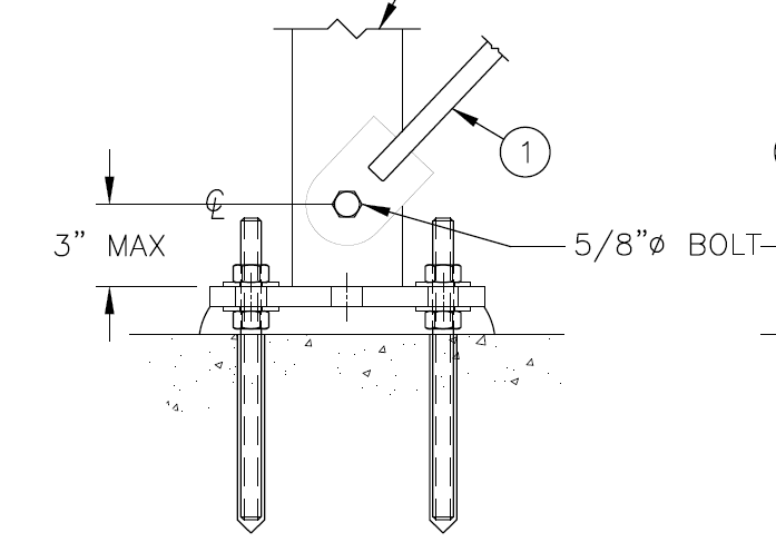
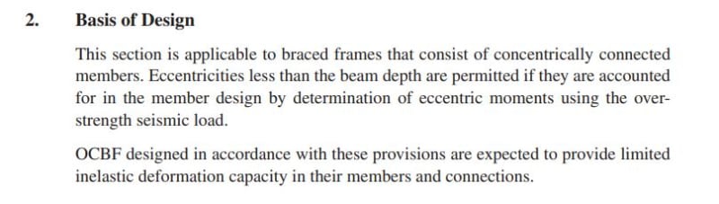
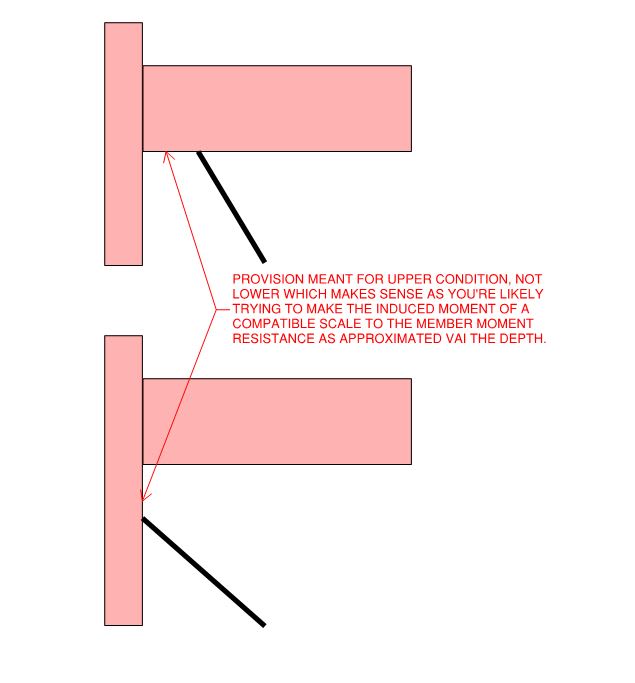
The detail shows a 3" offset from the baseplate to the bolt hole to maintain an eccentricity less than the beam depth as specified in Section F1.2 of the Seismic Provisions. Because the column is bolted to the foundation and there is no beam, 3" was deemed reasonably less than the 4" column depth.

Due to field issues, the contractor requested this 3" be increased to 6". The columns and base connections have no problem with the increased eccentricity.

The question is, at the base of a column, what is an appropriate allowable eccentricity given there is no beam?

Thanks in advance!
 
Replies continue below

Recommended for you

There's nothing very explicit here for base-of-column eccentricities. I wonder if F1.2 is simply commanding you to "keep the eccentricities to a minimum".
As long as you use the overstrength factor on it and you are within the realm of what a beam depth for your frame would be (say in the story above) then you should be fine.

Also - is your rod eccentric from the column as well since it is attached to the column side?

 
It's definitely fair game for interpretation but my inclination would be to follow your original assumption: max eccentricity = 4" = column depth. My read of the provision is that the eccentricity is meant represent a connection point offset horizontally along the beam, not one offset vertically along the column (extremely rare anywhere other than at the foundation). In your case, I think that it's most analogous to be treating the column as though it were the beam affected by the eccentricity since it is my expectation that the goal is to enforce some kind of compatibility between the resulting member moment and the member capacity (indexed to member depth). That goal only makes sense in your situation if the column depth is what is being compared to the eccentricity.

All that said, I consider OCBF design to be pretty much free for all, cowboy country where you can do as you please so long as it's rational and the numbers check out. I'd not sweat this myself unless I feared a challenge from an A-game AHJ reviewer etc.

c02_irvqrh.jpg


c01_kwuryk.jpg
 
Is that a through bolt or a blind bolt for connecting to the HSS face? Is the brace only to one face of the HSS column? If it were me, I'd rather weld a gusset to the centerline of the HSS face & base plate below and extend the base plate as required and use a clevis pin connection to eliminate the torsion you're going to induce at the base of the column. Use chapter K to evaluate the HSS face for the connection. Obviously depends on what your constraints are.

BAretired brings up a good point, I'm not sure what, if any, out of plane eccentricity is permitted in CBF connections.
 
It seems to me that the anchor bolts will want to restrain the rotations caused by this eccentricity. The bolt demand skyrockets.

Are you still considering it a pinned base?
 
Thank you all for the replies!

JAE - Yes, my initial thought was to keep the eccentricity to a minimum. 6" does not sound unreasonable to me but I want to make sure we are at least meeting the intent of the code. And yes, the rod is through bolted to the face of the HSS4x4x1/4. This does create an eccentricity of 2" but was accounted for in the anchor design.

KootK - Those were my thoughts as well. The intent of the code is to limit the eccentricity while accommodating the connections. This is an unusual structure with light loading and tons of redundancy. I appreciate your practical approach to the problem. Since this is a modification, I am not sure how much scrutiny there will be.

BAretired and strucbells - The brace has an eccentricity in two directions because it is through bolted to the face of the column. The forces in the braces are around 3 kips (ultimate but without over strength) so they are relatively lightly loaded. This small eccentricity was factored into the anchor calculation. Ideally, the brace would connect to a gusset plate. However, due to some wall framing that is in line with the framing, it was not possible to install braces with a gusset plate at the center of the column. Also, the steel is hot dip galvanized so welding at this point is not practical.

JLNJ - The extra forces due to the eccentricity were accounted for in the anchor design. Because the forces are relatively small (3 kips ultimate without over strength) the anchor design was not adversely affected. And we modeled the connections as springs so they do take some moment but are not fully fixed connections.

 
I have seen in seminars where the modified workpoint has to fall within the column or beam footprint to be considered a concentric braced frame. So if you have a 4" wide column, the maximum eccentricity would be 2" (or if you extended your brace centerline to the top of the baseplate, graphically, you would want to see it within the 4" column footprint).

Of course, this is mostly in terms of SCBF, so I don't get to do too many OCBF's anymore.


Status
Not open for further replies.
Back
Top