That is a gable roof shown in elevation, right? For the stated example, I might try to do a pair of three sided diaphragms. Seems easier.
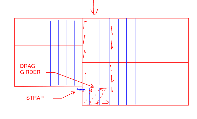
I agree with Aesur's shear blocking at the horizontal offset, and I don't think it's quite as hard as KootK is thinking it is.
1) I wouldn't be too worried about this. But see my note below about wind/seismic. May be more important where the earth moves. So long as the diaphragm has the shear capacity that the second drag truss would usually need to take, I let it go.
2) Maybe, maybe not. My average roof diaphragm is waaaaay below capacity. Standard attachment is enough to do quite a bit where I am.
3) Not necessarily. For one thing, Simpson has their new nail gun coil straps with dimples to help set a nail properly with a gun. They also have straps that can bypass the truss and be nailed to the face of the blocking.
H2A turned on its side, for example.
4) This would be a nice detail, probably never built scenario. But who knows, maybe you'll get a carpenter that pays attention to drawings. I don't know that it's that critical, though, unless we're talking 8:12 or steeper. So for folks in Canada, probably matters. Here and south, less so.
5) Probably need that anyway? Else how is your shear getting to the shear walls in the long direction (not shown in OP's sketch).
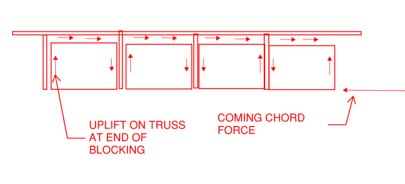
6) This doesn't bother me. Intermittent blocking can still transfer compression. Depending on workmanship it won't be quite as efficient, but it still works. The coil strap is there because the blocking is intermittent and can't transfer tension. Or am I misunderstanding your meaning?
7) I can see this causing some localized issues. Offset makes continuous strapping a challenge without the need for extra blocking and waste, and I agree all those toe nails would be problematic unless you can ensure truss verticals and space out the nails. Otherwise, the clips are probably the best bet.
8) Easy enough, but added cost.
I think it's strong enough and probably stiff enough to prevent collapse in most scenarios. When I start doing this kind of detailing, I'm rarely worried about serviceability (unless it's a really unique situation). This is the sort of detail that prevents that initial movement of the proverbial zipper. If the zipper doesn't come undone, the house doesn't come apart. The sort of storm that would cause this detail to matter (based on observation of similar houses with absolutely zero comparable detailing and what they have survived) falls squarely in the "I don't care about your drywall cracks" and "what do you mean you're not evacuating?" areas.
For the general case, I tend to fall back on the IRC for some 'lower bound' solutions. As long as I'm not getting into high capacity, blocked diaphragms, I use the IRC's braced wall rule for offsets. So as long as the jog in the wall isn't more than 4', I don't usually do anything too crazy. I'll run blocking and a strap to overlap the offset, but I won't get into serious sub and transfer diaphragm detailing. But then I'm mostly concerned with wind, and under 7-16 I'm actually getting quite a few houses coming in as Seismic Design Category A.