Continue to Site

Eng-Tips is the largest engineering community on the Internet

Intelligent Work Forums for Engineering Professionals

  • Congratulations SDETERS on being selected by the Eng-Tips community for having the most helpful posts in the forums last week. Way to Go!

One-Sided Welds - An AISC question

Status
Not open for further replies.

JAE

Structural
Jun 27, 2000
15,543
We recently came across an question in steel weld design and forwarded this to AISC for their response.
I thought I'd post it here to see what others think:

[blue]We are trying to design a beam-to-column connection using a seat under the beam. The concept is to also include a top flange clip angle to laterally stabilize the beam and also to help the beam take some significant out-of-plane lateral load into the column.

However, there appears to be an inconsistency in the AISC Steel Manual and Specification (360-16 – 15th Edition Manual). In the commentary of Section J2.2b, there is a discussion about single sided fillet welds in joints subject to rotation about the toe of the weld, or the weld axis. The commentary illustrates this with Figure C-J2.3(b). Also, in the manual, on page 8-17, there is also discussion of one-sided fillet welds, referencing Figure 8-10, and showing the concern for the crack initiation at the root of the weld due to the plate-to-plate interface creating a stress raiser point.

However, in Part 10 of the same manual, on page 10-69, for Unstiffened Seated Connections, Figure 10-7(b) clearly illustrates a top flange brace angle with welds only at the toe of each angle leg, one to the column and one to the beam. The beams in this illustration will rotate under load, pulling the angle such that the toe of the weld at the top of the angle will rotate as warned against by the previously quoted sections.

We have also seen other AISC resources, details, etc. that also suggest that the angle toe-welds like this are permissible.

Can you clarify why these may or may not be inconsistent? Is there a particular aspect of the angle welds in Figure 10-7(b) that allow this? Is there perhaps a limit on rotation that a weld can take despite being a single-sided weld?[/blue]
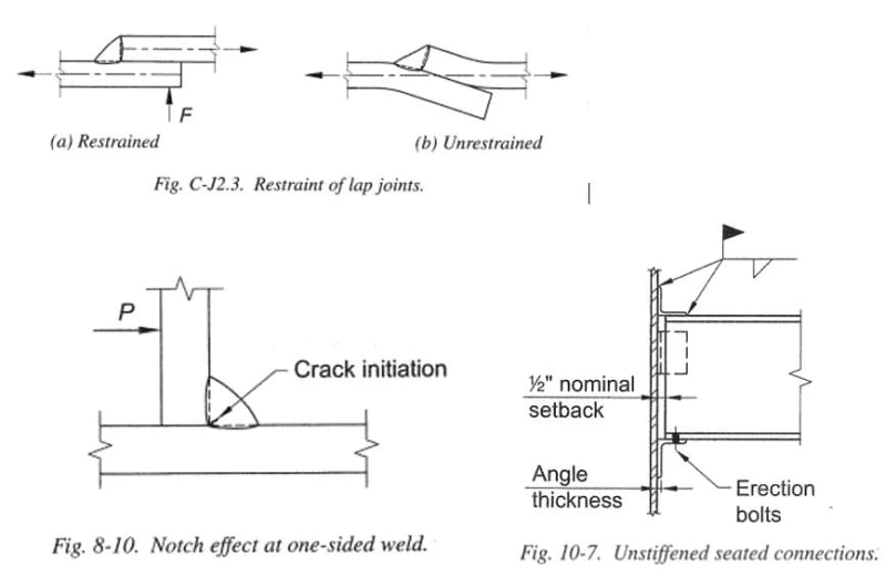
AISC_figures_ptv6uu.jpg
 
Replies continue below

Recommended for you

There was some discussion about one sided welds some time ago at the AISC task committee meetings. It was brief and I don't necessarily remember it perfectly.

But, the AISC design guide on HSS connections has a penalty factor on HSS fillet welds where they don't allow you to take the J2-5 increase based on load angle. The discussion was something like HSS welds are the only one sided welds where very much testing has been done. And, that there is a concern that the limit of weld strength may be a function of being a one sided weld more than being part of an HSS connection.

It made sense to me. Therefore, I haven't used the J2-5 increase in cases where we have a single sided weld like that. I wouldn't be surprised if it makes it's way into the code eventually. But, I haven't been at the code meetings for about two years. So, I'm not sure if it's been discussed during this code cycle at all.
 
Note: I don't have a problem with one sided connections. I just make sure I don't use the J2-5 increase at all. Maybe for a case like your connection, I'd be a little more conservative with the weld strength calculation. But, it doesn't appear that your weld orientation is subject to these concerns or the concerns about rotation about the toe of the weld.
 
But, it doesn't appear that your weld orientation is subject to these concerns or the concerns about rotation about the toe of the weld.
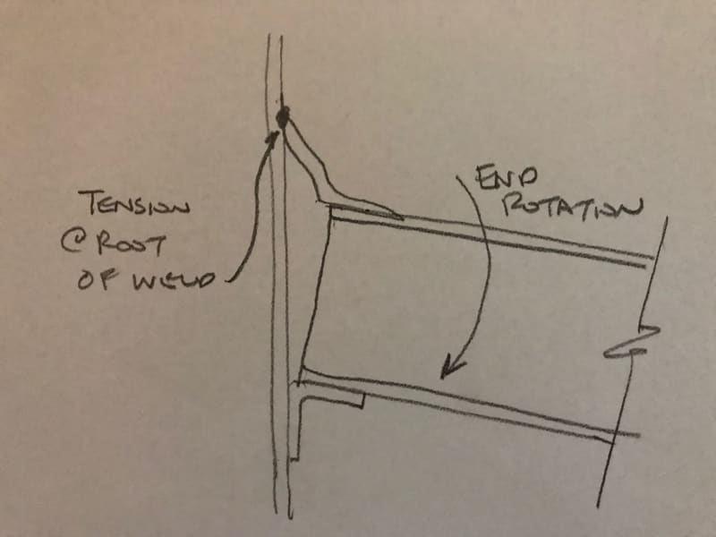
In the lower right figure (10-7) when the beam is loaded it will rotate the ends such that the top angle is pulled away from the column.
This creates a pull in the weld very much like that shown on Figure 8-10.

 
Yeah, I see that, but is that weld even loaded. Doesn't the vertical weight / beam shear go almost entirely to the lower angle? With the upper one there for stability, but without any real load applied to it. At least not in the direction that's cause for concern.

If this were designed as a moment connection, that weld on the upper angle might be a problem. But, we really are only talking about a shear connection here. Right? Maybe you could bolt the angle to the column instead to set your mind at ease.
 
Josh - when the beam is loaded the center of the beam span will drop lower.
This means that there is a rotation at the end of the beam.
The top beam flange will translate away from the column, pulling the angle, and thus bending the top angle tip weld about its axis exactly like the example in 8-10.

Yes, all the vertical weight of the beam (beam shear) goes into the lower seat angle. But the flexure of the beam, and the resulting end-rotation of the beam, definitely causes that one-sided weld to be stressed in tension at its root.

The interface between the vertical angle leg and the face of the column is like a slot - a re-entrant slot that creates a stress riser in the weld at its root.


JAE - I see what you mean, but if this is designed as a simply supported beam (or at least this support is idealized as a pin), I should think your beam stiffness should be sufficient to prevent any significant flexure in the angle and make any rotation about the toe negligible. Maybe I'm wrong - what's your calculated rotation at the support?

If it is a problem, what about slotted holes in the top flange of the beam? That way, the beam is allowed to rotate without pulling on the angle, but the angle can still take your out of plane loads. If you do this, you could even put returns down the side of the angle to better resist the out of plane forces.

Interesting point about the apparent contradiction. I'm still using the 14th edition, and the crack initiation diagram is Figure 8-8 there, but the explanation is very lacking. Not sure if they expanded on it in the 15th. Maybe AWS D1.1 has some answers?
 
I did get an answer from AISC but thought I'd post this question here as well to see what you all think and/or know.

phamENG - we considered that for a typical beam, the lateral translation of the top flange at the beam end due to beam flexure could be very small...in some cases, though, it could be larger depending on beam depth, span and loading.

The concern is that AISC, or others, haven't presented any guidance on just how much "small" rotation could be tolerated by the weld.

Your ideas of welding down the side of the angle would certainly take care of the issue...but it would then also begin to resist the rotation - sort of like a moment connection (either FR or PR), which we wouldn't want to do.


True, but if you provide slotted holes in the top flange of the beam, the restraint essentially goes away.

What did AISC have to say?
 
Well...slotted holes are fine - but if there is a small amount of catch on the bolts sliding, which there very well could be, the weld would get stressed to some level...and per AISC we don't know what amount of stress becomes a concern.

Their response:

[blue]There are things that intuitively make sense from a mechanics/engineering point-of-view and there are things that clearly are bad ideas. Between these two extremes there are a lot of conditions that are subject to engineering judgment.

When rotation is applied to a fillet weld about its axis (the toe, root) this places stress that it difficult to quantify, on an area of the weld (the root) that in some respects can be viewed as a crack (the notch effect shown in the figure you included) and that is difficult to inspect. Such conditions promote fracture. In fact when welds and welders are qualified one of the tests used involves the introduction of just these sorts of stresses with the intention of breaking the weld. Most engineers want to avoid conditions that are intended to cause things to fail. Therefore, it is best to approach the use of single-sided fillet welds with some caution.

Your questions hit on one of the aspects that might explain why it is generally okay to use single-sided fillet welds for the stability angle. While I cannot point you to a limit on the rotation a single-sided weld can take (and I suspect determining such a limit in a meaningful way would be difficult), clearly single-sided welds have some ability to resist such effects. In the tests described above considerable force is applied to the joint with a heavy hammer to cause the fracture. It is useful to think about it from the other direction as well. The rotation that can be applied to the weld is limited. First the simple beam end rotation will be a function of the span and the load and will be limited based on the strength of the beam (sometimes referred to as a self-limiting condition.) The angle is generally also kept small to limit the load that can be delivered. The Manual states, “A 1/4-in.-thick angle with a 4-in. vertical leg dimension will generally be adequate.” The idea is to provide a connection that is effective in preventing the beam from twisting about its axis, while allowing relatively free end rotation. The single-sided welds will be subject to some rotation about their axes, but the effect will be small. A significant history of adequate performance also indicates the practice is okay.

If your intent is to resist significant out-of-plane load, this might cause you to use a thicker and longer angle. This will likely increase the demand on the welds relative to rotation about their axes and this could cause a problem. It is certainly worth thinking about.

I have addressed your questions below in red:

Can you clarify why these may or may not be inconsistent? [/blue][red]There is no prohibition on the use of single-sided welds. While some of the statements and examples may point in divergent directions, I believe the underlying philosophy is consistent. I have provided some further explanation above. [/red]

[blue]Is there a particular aspect of the angle welds in Figure 10-7(b) that allow this? [/blue][red]Yes. I have provided some further explanation above. [/red]
[blue]Is there perhaps a limit on rotation that a weld can take despite being a single-sided weld? [/blue][red]Yes. I have provided some further explanation above. [/red]

[blue]Please let me know if you have any further questions.[/blue]


JAE,

What is the expected rotation of the beam end absent the restraint provided by the upper angle?

I understand that your sketch is exaggerated for illustration purposes, but I would expect that the angular rotation of the upper angle about either of the single-sided welds (to the column or beam) to be about HALF of the beam rotation (by symmetry, unless the welds were of significantly different size/length). Also, I would expect the legs of the angle to bend rather than the heel as the fillet area where the legs join is significantly thicker and will be more able to resist the legs spreading apart at this location.

So if the beam rotation is SMALL, the rotation at each of the welds should be ~SMALL/2.
 
jdonville - that was my thought, but JAE is right that this line of thinking only works for some beams. For the general case, a larger tolerance is needed. For instance, if you have a 36" deep roof beam allowed to deflect to L/180 with the bottom flange sitting on a bearing seat and slotted holes in the shear tab, you'll end up with as much as 0.80" of movement in the top flange. I could see that causing a problem. This is an extreme situation, but as JAE mentions there's no definition of "too much."
 
Yes - the problem here is that AISC provides zero guidance on how much is too much.

jdonville - even if "small/2", for a brittle weld with a slot-stress-riser small/24 could be too much and fracture the weld...we just don't know.

 
For 0.8" movement at a 36" beam, rotation will be over 1.25 degrees. Not sure that that qualifies as "small rotation" anymore...

I am used to allowable service deflections of L/360 or 1/4" total, whichever is lesser (falsework for bridge deck construction).
 
jdonville - deflections limits within buildings vary based on use of the member and type of loading applied. Assembly floor with some sort of specialty tile floor - L/700 may not be unreasonable. Roof beam considering full dead and live load effects and not supporting a ceiling - L/120 is allowed by code. So end rotations can get significant.

Thanks for bringing this up, JAE - good to keep in the back of our minds as we're detailing until somebody does some more research.
 
We use angles like this - with top leg tip welded to a plate - for continuous edge angles at roof diaphragm perimeters.

Any rotation in the supporting framing for the edge angles - i.e. if the roof framing causes this sort of prying action on the weld - could conceivably fracture the weld and diminish its effectiveness in transferring longitudinal diaphragm shears into the exterior walls, etc.

Just very disconcerting to realize that the miles of angle tip welds we've used in the past are possibly subject to fracture with minimal movements.

 
Very good point. It may be worthwhile specifying an intermittent weld between the edge of the flange and underside of the angle/bent plate in those situations to restrain the connection and prevent crack propagation from the "notch." Though hopefully there's a better idea, since nobody likes overhead field welding...
 
PhamENG -

Or, just a return down each side of the angle. Then you have some quantifiable resistance to rotation to relieve whatever stress that weld would have seen.

Now that I think about it, there was a long discussion about a very similar issue related to a RISAConnection some years ago. When I have some free time later, I'll try to find that thread.
 
Josh - my statement was referring to JAE's latest post about continuous edge angles which effectively have no "sides".

As for using that on the beam connection, that was part of my previous idea but JAE correctly pointed out that it would turn it into a Partially Restrained Moment Connection without a reliable means of releasing the longitudinal stresses elsewhere, which is not what he's going for.

 
Status
Not open for further replies.

Part and Inventory Search

Sponsor