Continue to Site

Eng-Tips is the largest engineering community on the Internet

Intelligent Work Forums for Engineering Professionals

  • Congratulations pierreick on being selected by the Eng-Tips community for having the most helpful posts in the forums last week. Way to Go!

One Way and Two Way Load Distribution in Tekla Structures 1

Status
Not open for further replies.

Tygra_1983

Student
Oct 8, 2021
125
Hi all,

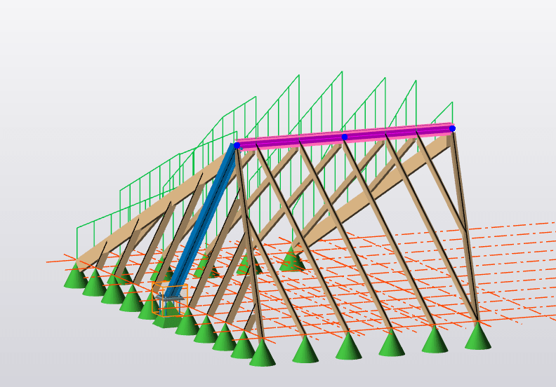
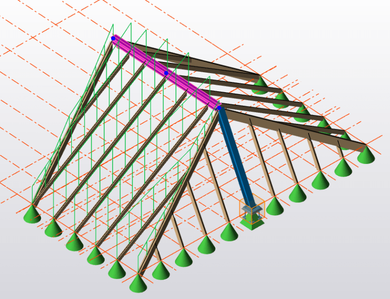
I am wondering if anyone on here has experience with Tekla Structural designer and knows how to switch between one way and two way load distribution? Because I have panels in my structure with area loads and the load is going only one way even though the dimensions are such that the load should be going in two ways.

Many thanks.
 
Replies continue below

Recommended for you

It has been while but click on the slab and review the properties/general tab. There's a button to check for two-way decomposition. I have used it in years so I can't tell how it's like in newer versions
 
Hi BulbThe Builder, thanks, that works. However, what about for a roof panel? I can't find anything to switch the loading to two way.
 
Actually, it's better to go into more detail.

The reason for the original question was because I have a simple structure and for some reason certain members don't seem to be taking any load when they should. I thought perhaps it was because the roof panel which the areas load is applied is only distributing the load one way.

Please observe the two pictures:

p1_qwy5xb.png


p2_i8iyv4.png


If you see the ridge beam highlighted in purple/pink, the load does not seem to be acting on this member. I have no idea why this is I would like to know the load that in takes in either point loads from the rafters or a UDL.

Do you think you could help?
 
It been so long since I used Tekla that I don't know where to start from. Are there no point loads on the ridge when you run your model?
 
We have a slab and roof panel and those are modelled differently? correct? I think Tekla uses the panels and you have to use decomposition and "orientation". Can you take a screenshot of your roof panels or membrane ?
 
The load region only generates loads on the rafters, the rafters pass their end reactions to the ridge beam this occurs internal to the structure so will not be plotted as an applied load.

Going further your model has pin supports at the base of all the rafters and they have a relatively steep pitch. Since the pinned end of the rafters does not translate the axial stiffness of the rafters exceeds the bending stiffness of the ridge and the rafters are actually supporting your ridge beam. Since the rafters are in effect supporting the ridge at the same location on each side and the load region is loading the rafters each rafters reaction is being passed straight through the ridge and becoming an axial load in the opposing rafter.
 
@Celt83, I am guessing using a roller support at one end of the rafters will be ideal then?
 
A little tricky when modeling the full stick built hip end, really the roof diaphragm is going to provide your horizontal reactions so need to find a good way to relate that to discrete support locations. I’d probably start with applying rollers to each rafter support in the direction perpendicular to the supporting wall and see what my deflected shape, shear diagram, and moment diagrams look like.

It is also not clear in the screen clip if the ridge beam has a support defined at the end opposite the bent.
 
Status
Not open for further replies.

Part and Inventory Search

Sponsor