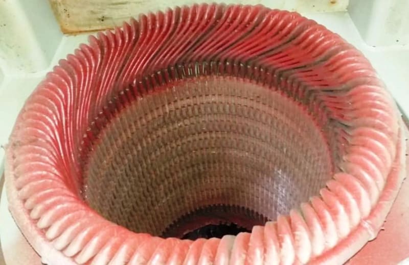
That is a head scratcher all right.
There are 18 equally spaced discolored areas, correct?
I claim that if this condition was related to normal operating voltage stress, then there would only be at most 9 locations. Let me explain my logic...
6-pole 18 groups. Groups are connected in alternating magnetic polarity:
A B' C A' B C' A B' C A' B C' A B' C A' B C'
If we label each group by an ordered pair of it's two terminations: (line neutral) for positive mag polarity and (neutral line) for negative mag polarity, then we have:
(Aline Aneutral)(Bneutral Bline)(Cline Cneutral)(Aneutral ALine)(Bline Bneutral)(Cneutral Cline)...
If we look at the 18 interfaces ")(" between coil groups: they are going to alternate between two patterns:
1 - one interface has two neutral end connections ...Aneutral)(Bneutral....
2 - the adjacent interface has two line end connections ....Bline)(Cline...
Only interface type 2 has a line end connection.
Do you agree? (maybe I am missing something).
If you guys agree, then we don't have the highest voltage stress at 18 equally-spaced locations around the circumference, we only have it at 9 equally spaced locations.
In that case it seems the pattern has nothing to do with normal operating voltage stress.
Even if I'm wrong on that, it certainly doesn't look like partial discharge. It's way to uniform accross the knuckle and down the slot for that.
You call it “blackening”. Is the red color the vpi resin color or something applied afterwards? To me it looks more like a surface red coating has disappeared to reveal the original vpi'd coil tape color below.
EDIT
Above I assume the 6 groups per phase are in parallel but that may be wrong.
If there are any series group connections then I'd think it is even fewer line end connections, although there are more possibilities for phase-to-phase combinations because there are also fewer neutrals.
It seems possible we have 18 group interfaces that have high voltage stress between adjacent coils at the end of each group.
If this scenario were applicable, the discoloration would have to be driven by partial phase to phase voltage differences between coils at the end of each group rather than phase to ground voltages at line end coils... still seems odd from the appearance although I see that each location involves two adjacent coils discoloring.
Can you describe how the groups are connected?
=====================================
(2B)+(2B)' ?

