Continue to Site

Eng-Tips is the largest engineering community on the Internet

Intelligent Work Forums for Engineering Professionals

  • Congratulations IDS on being selected by the Eng-Tips community for having the most helpful posts in the forums last week. Way to Go!

Opinions on non-standard and non-contiguous MV drive configuration

Status
Not open for further replies.

jraef

Electrical
May 29, 2002
11,342
I'm being asked to bid on a project that involves retrofitting a Medium Voltage VFD into an existing facility that has a MV MCC in place already, and there is no space in the room to fit the MV VFD in it's entirety. The VFD is a VSI drive with an 18 pulse front-end, so it has a large transformer and rectifier section, followed by an inverter section with the DC bus caps etc. In the engineer's mind, he wants to separate the two components; the transformer/rectifier on one end of the room, the DC bus section / inverter on the other end of the room at either end of the MV MCC, a distance of approximately 20ft, with a cable/conduit connection at roughly 6kVDC between the two. They want to lay the MV DC conduit on top of the existing MCC, against the wall.

I'm not really comfortable with this arrangement and think there may be unforeseen regulatory issues (it's here in the US, so NEC applies), such as whether or not the line fuses FEEDING the rectifier would count as Branch Circuit protection for the DC feeder circuit, i.e. is fusing the AC side (ahead of the transformer) providing protection for those conductors. As a complete system all in the same enclosure it is like that now, but what's different here is that have we created a "feeder" circuit here because those conductors left the enclosure? This is new ground for me, I'm looking for opinions mostly.


"You measure the size of the accomplishment by the obstacles you had to overcome to reach your goals" -- Booker T. Washington
 
Replies continue below

Recommended for you

Howdy Jraef,
I have seen many large MV ADSs split like you have mentioned, but these bad boys are generally 15,000hp and up. In this situation usually the transformer is liquid-filled and located outdoors, the remainder is usually located indoors. The last time I looked into one of these splits, the OEM was very concerned wrt the length of the cabling between the two sections.
I have not seen this done on smaller air-cooled vsi drives (ie < 9000hp), but there is no reason why it could not be made to work.
Have you contacted your drive OEM to see what they can do for you? I'm sure that the TIC will be a tad higher (maybe +25%).
BTW: How large is the drive in question (ie hp)?
GG


"I have not failed. I've just found 10,000 ways that won't work." Thomas Alva Edison (1847-1931)

 
I have seen Robicon 6 kV systems that seem to avoid a bulky transformer. I didn't look closer, but that is what the salesperson said (pls note P.C.). Or was it just salestalk?

Gunnar Englund
--------------------------------------
Half full - Half empty? I don't mind. It's what in it that counts.
 
Howdy Slog,
It was likely a current source drive.
GG
ps I thought that Robicon was bought by Siemens, and that all of the Siemens/Robicon drives were voltage source type. How long ago did you see this drive?

"I have not failed. I've just found 10,000 ways that won't work." Thomas Alva Edison (1847-1931)

 
It was only a few years ago. And, yes - it had a Siemens stamp on it. But it was definitely a Robicon. With cascaded multi-level output. And a VSI, as far as I could see.

Gunnar Englund
--------------------------------------
Half full - Half empty? I don't mind. It's what in it that counts.
 
Howdy Skog,
Well then it must be a Siemens (ex Robicon) 'PerfectHarmony' 18-pulse voltage-source ASD with integral transformer.
GG

"I have not failed. I've just found 10,000 ways that won't work." Thomas Alva Edison (1847-1931)

 
This one is "only" 500HP. In the older Robison CSI drives like this that I witnessed, the transformer was outside but the feed into the building was AC in the the 18 wires going TO the rectifier, not the DC from the rectifier to the inverter.

This configuration is apparently the brainchild of the Engineer on the project, who did not sign the drawings I was given (it's still at 90%, so I'm cutting them some slack), ergo I cannot yet ask him/her where they got the idea. No mfr is mentioned in the sketchy specifications yet, but being that they want 18 pulse for 4160V it has to be based on one of the NPC topologies still out there, not the Cascaded H Bridge designs like Siemens/Robicon or most others (now that the original Robicon patent expired) are selling. A CHB would be 24 pulse at 4160V, but more importantly you no longer have a single DC bus, you have separate LV cells in series, so there is no way to do this separation at all. One of my concerns here is that with all these new CHB designs being released now by virtually everyone, even if this is viable with an older design concept, the field of available options might be limited now and this was an indirect way of one of the remaining "old school" VSI vendors to lock in their spec because they know it can't be done with a CHB. I'm going to propose that instead of going through this rigamarole of having the VFD split in two on opposite sides of the MCC, they simply move 3 of the exiting MV MCC sections from one end to the other so that all of the available space is at the one end, allowing plenty of room for a complete new VFD. Yes, there is more conduit work involved, but I still think that ultimately it would be cleaner. The 20ft run of 6kVDC worries me.

Thanks for the opinions so far.


"You measure the size of the accomplishment by the obstacles you had to overcome to reach your goals" -- Booker T. Washington
 
Hi Jraef,
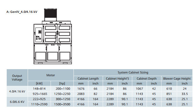
500hp drive puts you into the smallest footprint for the Siemens M VASD (Gen 4). I am not sure if Gen 5 is out yet, but I heard that it has an even smaller footprint. Of course, Toshiba also flogs a similar type of drive, but with the option of an outdoor enclosure. I have used these in Northern Canada. Could be an option if you can't find any indoor space.

2017-05-17_7-43-22_ad46bc.jpg

GG

"I have not failed. I've just found 10,000 ways that won't work." Thomas Alva Edison (1847-1931)
 
Jeff said:
In the older Robison CSI drives like this that I witnessed, the transformer was outside but the feed into the building was AC in the the 18 wires going TO the rectifier, not the DC from the rectifier to the inverter.
That's what I was thinking. Will the code allow primary protection only for a multi pulse transformer?

Bill
--------------------
"Why not the best?"
Jimmy Carter
 
M2LC has an output like a CHB, but runs with a single DC bus between the rectifier and inverter so the converter can be separated from the inverter.
 
Thanks LH, that's a new topology for me and I see what you mean. Same core concept behind CHB with multiple small cells to make up the PWM output, but all fed with DC instead of AC. That might be what he is basing this on. I still have my concerns with running that MV DC link so far across the building however.


"You measure the size of the accomplishment by the obstacles you had to overcome to reach your goals" -- Booker T. Washington
 
Generally speaking, most VFD suppliers are reluctant to idea of separation the inverter(s) from the front end converter. We had a 3 MW VFD systems with 4 inverters, and decision to separate inverter sections has been made only after modeling of overall DC bus extension system. The critical component was a cable link and its distributed capacitance and inductance. We used 2 conductors armored cable (MFG - NEXANS) with multiple cables in parallel. The modeling proved the absence of resonance in the vicinity of front end converter switching frequency.
 
Status
Not open for further replies.

Part and Inventory Search

Sponsor