Continue to Site

Eng-Tips is the largest engineering community on the Internet

Intelligent Work Forums for Engineering Professionals

  • Congratulations IDS on being selected by the Eng-Tips community for having the most helpful posts in the forums last week. Way to Go!

Orifice meter max differential pressure maximum question 4

Status
Not open for further replies.

reydR

Mechanical
Nov 24, 2015
8
I work for a natural gas midstream company and I am working on finding cost conscious ways to improve our design and need some guidance. A little background..

Some of the wells we are putting custody transfer meters on begin flowing at 100-300 MMCFD. Absolutely insane volumes. There are future projections of wells hitting 400 MMCFD at peak. Our operating pressures are around ~800 +/- 50 PSI depending on downstream compression. We currently use 0-1000" DP multivariable sensors, but only calibrate to a range of 0-500" and that was after begging and pleading to increase from 250". Well, I have asked to begin looking at setting my initial calibrations to 0-1000" to reduce construction costs and have been met with some resistance. For example, for a well coming on at 200 MMCFD, this would literally save us hundreds of thousands of dollars on one meter assembly by allowing me to set one 10" meter and set my DP to 0-1000" versus how it is now and installing a 16" header system and two 10" meters calibrated to 0-500".

I have lightly read API 21.1 and AGA Chapter 3 and I cannot find anywhere that says that expanding my DP from 0-500" to 0-1000" would be less accurate. Is there anywhere stating a point in water column at which unacceptable errors begin arise? If someone could point my in the right direction I would be most appreciative!

-Rey
 
Replies continue below

Recommended for you

The big concern is the flow rate leaving the velocity where the incompressible flow assumption in the derivation of AGA 3/API 14.3 is valid (i.e. where you can ignore dynamic pressure). This is typically taken as a 3% reduction in density (calculated with static pressure). Since 1000 inH2O is 38 psi, you are getting into a grey area at your 800 psig system. You could certainly go to 0-700 inH2O without introducing too much uncertainty, but any higher than that could be a problem.

Some authors claim that the incompressible assumption is valid in the AGA 3 equation up to a 5% reduction in density, in which case your 1000 inH2O calibrated range would be fine.

I used the 3% limitation when I was operating what seemed like a big field until I hear numbers like yours. My material balance showed 0.1-0.5% system loss between the wells and the CPD, so that density change limitation certainly kept the arithmetic valid, but I don't know if 5% would have also given me that kind of material balance. As I approached 3% on a well I became very careful about beta ratios. I never allowed greater than 0.72 on any meter, but at around 3% I backed that off to 0.65.

David Simpson, PE
MuleShoe Engineering

In questions of science, the authority of a thousand is not worth the humble reasoning of a single individual. Galileo Galilei, Italian Physicist
 
Whenever I've been involved in these calculations, a key factor in calculating the possible uncertainty from figures coming from an instrument such as your DP sensor is that the figures given by the vendor are as a percent of range., e.g. 0.1% of 250 is 0.25", but the same percent of 1000 is 1".

Now that might not make a huge difference when you add in the other factors which don't change, but what I do know is that when you're talking about fiscal / custody transfer systems you really need to have someone who lives and breathes the metering calculations and can tell you whether what you want to do will work or not or what the acceptable range of flow is for any of your systems. When it comes to money transfer, the other side will have such experts and their fee is normally negligible compared to what a 0.5% discrepancy on flow could be worth.

They are very big wells though....

Remember - More details = better answers
Also: If you get a response it's polite to respond to it.
 
gerhardl,
I am a huge fan of the V-Cone and have been easing them into the projects I've been doing. The big problem I see is that Engineers are pushing the technology without first slowing down to get the measurement techs on board. For example:
[ul]
[li]In a gas lift project the sum of the V-cones on a well pad were substantially different from the Orifice meter on the edge of the pad. I proved to the engineers that the orifice meter was junk (0.8 beta ratio, 3 elbows close coupled out of plane, too short, etc) and that without them the material balance was really good. The techs did not get to see the data and years later I heard one of them cite this site as the reason he won't use V-cones.[/li]
[li]In a project in West Africa the sum of the wellhead V-cones was 25% lower than the orifice meter in the plant. I looked at the RTU and the techs had selected orifice calculations instead of V-cone calculations, and they had a 100% methane gas analysis instead of the actual (70% methane) analysis. The techs response was "no one ever told us the calculation and gas analysis were different". In other words they were blocking the technology without standing up against it.[/li]
[li]In Queensland the measurement techs did not want to stock different meters for different wells and when the engineers shoved the V-Cones down their throat, they just picked a 4-inch 0.6 beta meter and put it everywhere. The minimum flow that the meter could measure was around 300 MSCF/day, but the wells were making 250 MSCF/day. I tried to get properly sized V-cones, but ran into the MOC/HAZoP/Critical Drawing Review/etc nightmare and gave up.[/li]
[/ul]
Bottom line of all this is that no one is going to put V-Cones on a 400 MMSCF/day well until they've had success with them on a few hundred 400 MSCF/day wells. Just the nature of this business.

David Simpson, PE
MuleShoe Engineering

In questions of science, the authority of a thousand is not worth the humble reasoning of a single individual. Galileo Galilei, Italian Physicist
 
Just curious, are these meters on the wellflowline itself ? If so, are they not measuring dp in a 2phase / 3 phase stream ( gas + some condensate + some formation water) ? If so, how could these ever be good for custody transfer - many metering folks have tried this ( not for custody transfer, but just to get WGR and CGR ratios ) and failed miserably.
 
Hi zdas04 and georgverghese!

I fully agree with you zdas04!

The main problem with piping components as checkvalves, regulating and pressure reducing valves and all kinds of measurement devices is that all need to be dimensioned and selected to suite the actual flow and fluid parameters, at all operation conditions. All engineers 'know' this.

But! : The necessary information is very often not presented, given to late in the project, or made based on irrelevant parameters as pipe diameter, earlier experience from (quite) other cases, cheapest buying price (not performance and economical best over long time) and a lot of other non-engineering reasons.

As you said: technology improves, but not necessarily the quality of decision makers.

To georgverghese: you have to check all detailed parameters with a supplier if you want a detailed answer.

And yes, V-cone correctly mounted and calibrated can have a (fiscal!) accuracy better than many other measuring devices (including orifice devices), and over a far larger range, but will not be suited for all applications.

 
If these meters are located downstream of some separation / treatment equipment, the gas should be slightly superheated preferably. At the least the last upstream separator should be fitted with high efficiency / high turndown vapor / liquid demisting devices.
 
To get an exact measurement you have to know exactly what you measure.....!

 
All,

I want to thank you for some fantastic responses! Being that I sent this out a day or two before Thanksgiving, I figured I'd get one or two responses back. Boy was I surprised!

zdas04, I haven't looked too much into how working pressure affects DP and an acceptable range. I do know that after you get past a .6 beta, the margin of error begins to increase. Because of this it is the company's policy to not increase beta ratio past .6 unless there is an "emergency"

LittleInch, the percent error of span is something that I did not consider as well. I checked our sensor's manual and it is .1% of span. So calibrating to 500" WC would by like you said a .5% margin of error while increasing to 1,000" WC would be a 1% margin which is definitely pushing the limits, especially with the other inherent errors in our system.

gerhardl, I have looked into V Cone and the biggest issue I see is that there is no easy way of changing beta ratio. With orifice I can just switch plates. V Cone you have to pull the entire spool. With the wells depleting at a rate far faster than normal (that 200 MMCFD well will drop to 100 MMCFD after 6 months). After four years the wells appear to deplete to 25% of initial flow.

In response to your later comment, you are correct. I am not given the correct flow rates from the producer until a week or two from when they want to turn the well on. And many times even that number is incorrect. It is very frustrating. This fact alone is probably the most frustrating part of my whole job.

georgeverghese, To answer your first question, yes. The producer has their own check GPUs that measures and drops a lot of the condensate out and then we have our meter. I might not be understanding the terminology though. We definitely account for gas makeup and how much water vapor (A LOT) is in the stream. Is that what you meant? I believe that we actually charge the producer based on gas compressed at the compressor station itself. The gas we measure is typically around 70 degrees F.
 
A big source of error may be if there is (a) liquids dropping out of this gas stream upstream of this meter and pooling at piping low points (b) liquid carryover from the poor vapor-liquid separation at the last vapor liquid separator upstream.
Another source of error in custody transfer meters is molecular weight swings (due to variation in CO2 and N2 content in feedgas mostly from different reservoirs) and poor reliability from online GCs' - these are the bane of instrumentation engineers in many operating companies.
 
gerogeverghese, (a) yes this is a huge issue for us. Our carrier sits horizontal and we use the bottom ports as drains (operations techs are trained to flush those drains any time they are near the area. I've never encountered a dry meter. I have pulled orifice plates and found water lines 3" high on an 8" meter. But this is a whole different story..

Your second point about molecular weight swings I do not believe we have an issue on. The gas makeup is VERY consistent. Our newer meters do not even have chromographs because pulling samples at the beginning and then biyearly yield the same results.
 
I have rarely seen a 6-inch or larger orifice meter without indications of water dams. I put a self draining trap upstream of a 6-inch meter that looked like it had a major problem and got water, I think I got it all. I expected the reported production to change on the well when I got rid of the chance for water accumulation, but it didn't change at all. I'm thinking that the water damming is very transient and too short to really be worth chasing.

Even on the meter that I did the test on, I've never seen standing water dripping off the bottom of a plate in a Senior fitting (and if standing water was a common occurrence then we would see moisture on plates). I think it looks like a bigger problem than it really is.

David Simpson, PE
MuleShoe Engineering

In questions of science, the authority of a thousand is not worth the humble reasoning of a single individual. Galileo Galilei, Italian Physicist
 
At these gas rates, it would make plenty of sense to the production accountants to eliminate or minimise liquid dropout, preferably before your customers finds out..
 
zdas04, not to stray off OP but when you say water dams, are you talking about something along the lines of the below picture? This is an 8" plate pulled from a meter that had been in service for about three weeks. It sure seems like a big problem.

20150610_184440_mwjna4.jpg
 
It does seem like a big problem, but ask yourself "how did the water line get that high on plate without all the liquid running through the hole?". The answer is a 50 gallon (for example) slug hitting the plate and over 50 mS splashing around until it was gone. What I found in my experiments is that you never end up with a liquid reservoir standing upstream of the plate because the energy required to maintain the fluid level is too high to be sustained. Liquid wants to run back down the inlet piping (when the supply pipe comes up from the bottom) or it changes flow regime and splashes out.

In my experiments the actual magnitude of the problem (because of the very short duration transients) was far lower than the damming line would make you think.

That is a very cool example though.

David Simpson, PE
MuleShoe Engineering

In questions of science, the authority of a thousand is not worth the humble reasoning of a single individual. Galileo Galilei, Italian Physicist
 
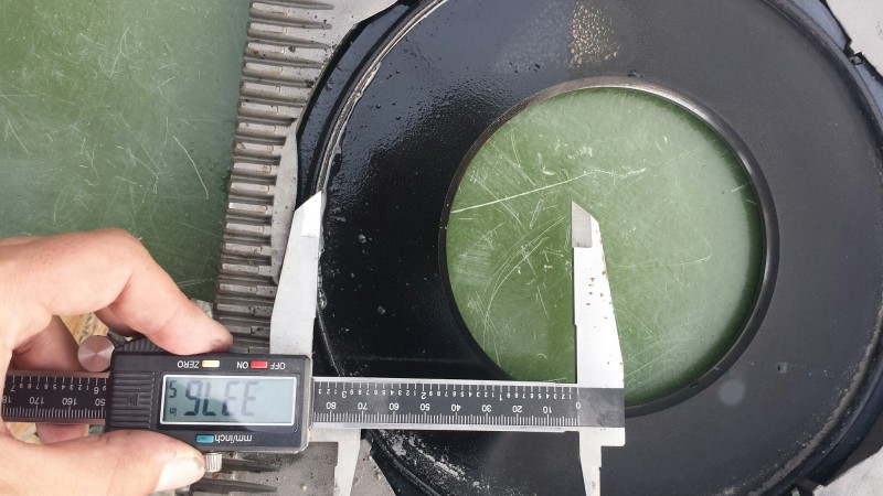
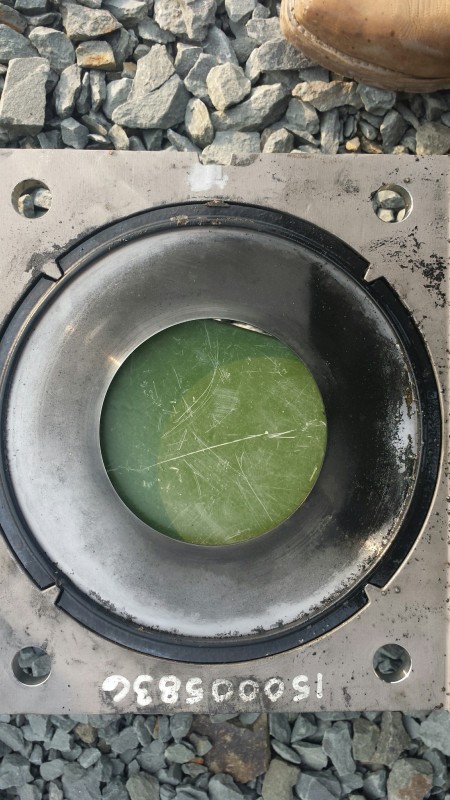
Was the OP in the photograph installed backwards?

Presumably, the dark, blackish coating is evidence of the water dam on the upstream side of the OP.

The bore surface is somewhat visible on the right side from about 1 o'clock to 5 o'clock.

Isn't the concentric ring (reflective surface at 12:30 to 1 o'clock) adjacent and to the outside of the bore surface the downstream beveled edge?

 
That is what it looks like. I've never seen a water dam on the downstream side of a plate.

David Simpson, PE
MuleShoe Engineering

In questions of science, the authority of a thousand is not worth the humble reasoning of a single individual. Galileo Galilei, Italian Physicist
 
The plate was note installed backwards. Look at the gear teeth on the plate carrier. The gear is on the downstream side, same as the beveled edge. It is strange, I'll admit. And I do not know enough about the process to understand why. But having pulled the plate myself, I can tell you that it was installed correctly with the beveled side facing downstream. Perhaps standing water? I will look through my pictures. I should have pictures of the upstream side as well, I will look for that.
 
Status
Not open for further replies.

Part and Inventory Search

Sponsor