Continue to Site

Eng-Tips is the largest engineering community on the Internet

Intelligent Work Forums for Engineering Professionals

  • Congratulations The Obturator on being selected by the Eng-Tips community for having the most helpful posts in the forums last week. Way to Go!

Out-of-Plane Loading on L-Shaped Beam (Fixed Ends)

Status
Not open for further replies.

calib

Marine/Ocean
Apr 30, 2023
2
I have a question about out-of-plane loading on an L-shaped beam, or a two-member frame, with fixed ends.

The problem I am working on is shown below:
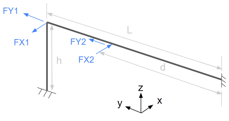
Lbeam_rzctjc.png


I can find resources on how to find the reactions and moments due to the FY forces but I am unsure how to find the reactions and moments due to the FX forces (out of plane).

Both beams in this scenario have the same I values. The FX1 and FY1 forces are acting at the same point and the FX2 and FY2 forces are acting at the same point, if it isn't clear.

I would greatly appreciate it if somebody could point me to a resource that explains how to solve this, or if anyone has any ideas on how to find the reactions and moments due to the FX forces.

calib
 
Replies continue below

Recommended for you

For FX1 and FX2, you could try applying the principles of determining the load split by equating displacements and rotations for the two beams on each side of an applied load. At the fixed ends, you will get reaction forces in the x and reaction moments about Y and Z (at FX1, moment in one beam will be seen as torque in the other). There are other elastic beam theories you could try.
 
You may have already read this but there is a previous topic than may be similar and could provide information


Edit:
There may be value in treating it as a single cantilever with a spring equivalent to the removed beam for each cantilever, evaluating for both and then comparing with a FEA solution. It's not something I've looked at in a long time so might be off base. May be others can confirm or challenge. The following are examples of potential interpretations rather than recommended solutions.

FEA:

macaulay step function:

FBD:

superposition:

The equivalent spring would be a rotational spring (based on the removed beams bending stiffness) rather than the direct linear spring of the previous links. The effective spring constant applied to the end of the cantilever might be K=3EI/L^3

Screenshot_2023-05-01_111116_qnbykj.png
 
Thanks for the responses, I have an idea of how to approach this calculation now.
 
it would help if you maintained a sigh convention ... FX1 is +ve in the -ve X direction.

Fy ... a small amount of Fy will be reacted at the base of the vertical leg ... depending on the deflection of the horizontal leg (under tension) ...
equate the tip deflection of a cantilever with a tip load dY with the tension deflection of the horizontal beam under Y1+Y2-dY.

Fx ... similarly equate the tip deflection of the vertical cantilever under a load of FX1+dX with the deflection of the horizontal leg.

"Hoffen wir mal, dass alles gut geht !"
General Paulus, Nov 1942, outside Stalingrad after the launch of Operation Uranus.
 
Status
Not open for further replies.

Part and Inventory Search

Sponsor