Continue to Site

Eng-Tips is the largest engineering community on the Internet

Intelligent Work Forums for Engineering Professionals

  • Congratulations SDETERS on being selected by the Eng-Tips community for having the most helpful posts in the forums last week. Way to Go!

Output CS

Status
Not open for further replies.

sushi75

New member
Mar 11, 2015
84
Hi All!

I'm trying to get my head clear with the output I get, in particular the displacements.

Is there a way in Femap to visualize what the output coordinate looks like? I've got a model defined in Cylindrical CS, and output in Cylindrical. But is this output CS defined relative to the elemenet material orientation?

Don't really see how T1 T2 T3 for displacements are defined!

Any help is more than welcome!!
Thaaaaanks
 
Replies continue below

Recommended for you

Hello!,
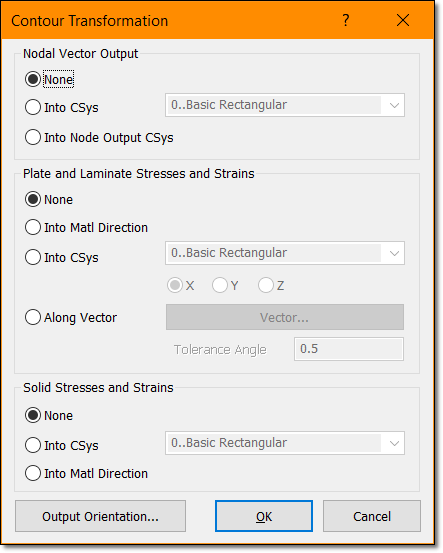
I don't suggest to define your FEMAP model in other CS different than global "0..Basic Rectangular", not need at all, later during postprocessing in FEMAP you can use "ON THE FLY" the option TRANSFORM and see results (displacements or Stresses) in any output csys you require, OK?.

transform-postprocessing_aqlatt.png


Best regards,
Blas.

~~~~~~~~~~~~~~~~~~~~~~
Blas Molero Hidalgo
Ingeniero Industrial
Director

IBERISA
48004 BILBAO (SPAIN)
WEB: Blog de FEMAP & NX Nastran:
 
Hi Blas,

I think this menu is pretty much was I was looking for.

My model has an axis of revolution, so both CS def and output CS are cylindrical.

But the problem I have is when I check the displacements on a given node, I don't manage to fully understand what T1 T2 T3 refer to.
Is T1 the radial displacement, T2 angular and T3 normal to the element?

In Nastran, there is a output CS defined on the element; I can understand it in rectangular CS , but cylindrical one is more difficult to get!

Thanks for your help!
 
Status
Not open for further replies.

Part and Inventory Search

Sponsor