Continue to Site

Eng-Tips is the largest engineering community on the Internet

Intelligent Work Forums for Engineering Professionals

  • Congratulations KootK on being selected by the Eng-Tips community for having the most helpful posts in the forums last week. Way to Go!

Overhead Crane Corbel Modelling on SAP2000

Status
Not open for further replies.

elinwood

Structural
Apr 2, 2012
34

Hi everyone,

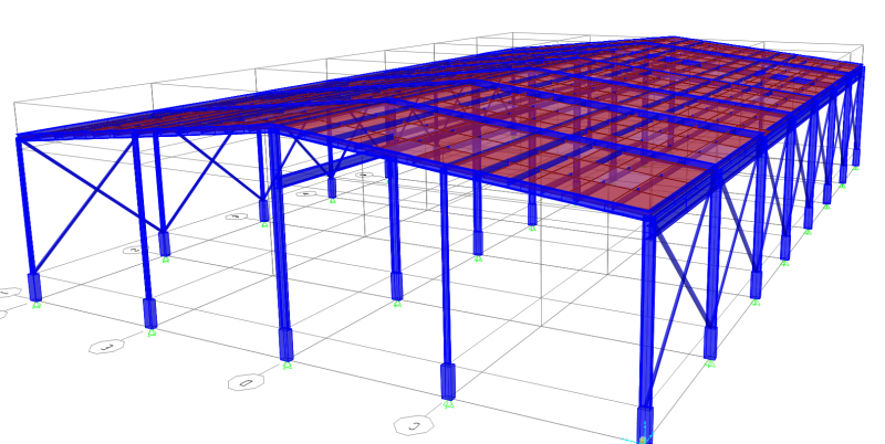
I am trying to model a warehouse with an Overhead Crane spanning about 14m (40ft). I have only inputted the dead and live loads of the warehouse, excluding any lateral (seismic/wind) loads but the model isn't working out. There's a problem with the top section of the column above the crane runway. For some reason, the moment is transferring from the crane to the top of the column causing the minor axis stress to be very high. Is this normal? I have attached the SAP2000 file of the analysis here in case anyone can help me. I'll upload snapshots of the model below.

Thanks!


 http://files.engineering.com/getfile.aspx?folder=c9791584-ab4d-457f-b8c7-710d388c9d8b&file=Design_Ratio.png
Replies continue below

Recommended for you

The file attached is the snapshot of the model overview

OH_Crane_Warehouse_qkjqb6.png


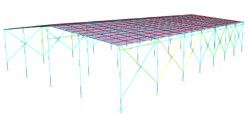
Design_Ratio_mzxos3.png


If you see on the second picture, the bottom section of the column is blue, but the top is yellow. This indicates that the column stress is higher on the top section. I have never encountered something like this before. Upon looking into it further, the section is yellow because of the minor axis stress - probably due to the crane load. I have put crane load in the middle of the section, 3.5m from the column (center of span)
 
Isn't there a lateral force (parallel to the rail, 10% of the wheel loads) as part of the bridge crane reaction, that would be resolved as weak axis bending in the columns?
 
Hi Jed,

Thanks for the response. I have not incorporated that load yet. I'm still struggling on how to input the crane loads into SAP 2000. I have been reading AISC's Design Guide #7 but I'm still confused. I have input the crane runway on the model, as you can see on the model. Do you think I should input the crane loads as Axial / Moment / Lateral loads on the column?
 
I think that you first calculate crane beam manually per aisc design guide 7, the crane beam is simply supported by two adjacent columns for the building. Then calculate the critical column support loads to the crane beam and apply those loads to columns in your fea model
 
If this is a pre-eng building, I'd just provide the loading. If non-preeng, then I would design the corbels 'locally' and not put them into a model. I'd apply the loads, eccentricities/moments into the model only. I wouldn't include the crane rails, beams, or corbels as part of the model.

Dik
 
dik, I've done even less for PEMB. "provide a 20T bridge crane with a maximum hook height of _____ and travel limits as shown on the drawings." The PEMB supplier knew exactly what to do.
 
The OP may not be in an area of the world which uses "pre-engineers". Some of us have to be real engineers.

elinwood, stress follows stiffness, and it is normal in a rigid frame for moments to be high at the knee. At a corbel, the bending moment distributes up and down in relation to the stiffness of the elements. But as to the minor axis stress, maybe your model is putting the corbel into torsion, thus applying a bending moment about the weak axis of the column. We normally don't consider the bracket to be in torsion, but rather make the crane runway beam stiff enough to preclude that.

For the column design, the crane should be positioned for maximum column loading, not at centre span. The appropriate loads should then be applied as point loads on the corbel. You didn't mention the capacity of the crane, but if it is a medium to heavy duty crane, a separate column or stepped column would be more appropriate than a bracket, which is only normally used for light duty cranes.
 
Without opening up your SAP model, I wonder if your crane girders are strong axis fixed to the weak axes of your columns. That would certainly draw weak axis moments into the columns for the reasons elaborated upon by Hokie (stiffness draws stress).

With the girders and the column segments coming in at a common node, it's quite difficult to achieve what you really want modelling wise which is:

1) The girders either side of the column joint fixed to one another with respect to strong and weak axis bending (assuming girder continuity).

2) No fixity between either girder's strong axis bending and the weak axis bending of either the upper or lower column segments.

3) Fixity between the upper and lower column segments with respect to both strong and weak axis bending.

If it turns out that this is indeed the problem, report back and we can guide you with respect to modelling improvements. One strategy could be to introduce real or fictitious longitudinal restraint to the crane girders such that the upper and lower columns could be weak axis pinned to the joint where they meet the girders.

Don't these systems normally have intermittent, in-line bracing between crane columns anyhow?


I like to debate structural engineering theory -- a lot. If I challenge you on something, know that I'm doing so because I respect your opinion enough to either change it or adopt it.
 
I don't know anything about the computer program that you are using, if it was staadpro, I could basically see that you don't have any moment releases. Your crane rail should not be transferring moments. Aside from that hypothesis, the only other thing I could think of would be your column can't handle the amount forces from the moment connection at the roof column interaction.
 
Status
Not open for further replies.

Part and Inventory Search

Sponsor