Eng-Tips is the largest engineering community on the Internet

Intelligent Work Forums for Engineering Professionals

Overload Performance of VFD in Hot Rolling Mill Application 11

Status
Not open for further replies.

Vikram 1971

Industrial
Sep 24, 2020
12
0
0
IN
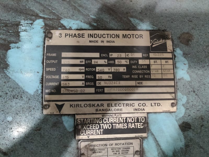
Currently using 335 KW 3 Phase Inductor motor (415V 563A 740 RPM) without any VFD in Hot Rolling Mill.
Thinking about investing in VFD to drive the above motor to enjoy saving due to VFD.
The motor operates in 20%-50% load for 50% percent of time. The current peaks up to 800-900 A for 1 seconds or less in every 10 seconds. Motor starting current is controlled via resistance shorting of slip Rings. (Motor runs idle-No load for atleast 20min in an hour)

My Question is -
1.) Whether VFD will be able to help in energy saving??

2.) I have decided a VFD (ABB Manufactured) rated for 600A. Will it be able to momentarily (less than 1 second) supply 800-900A during over loads???? What will happen in overload? will it Stop or Slow the process???

Attached the current reading during Normal operation.
Thanks in advance!!!!!!!!!
This is a big investment, I just want to be sure whether it worth it or just a marketing gimmick.


20210908_154845_gacu0w.gif
 
Replies continue below

Recommended for you

How do you think that a VFD will save money on a motor with a varying load? Is this a wound rotor motor?

--------------------
Ohm's law
Not just a good idea;
It's the LAW!
 
Thanks for replying
Is this a wound rotor motor?
Yes, it's a wound rotor motor. Slip rings are connected to resistance during the starting of motor which are ultimately shorted after starting operation of the motor.

How do you think that a VFD will save money on a motor with a varying load?
During the idle operation i.e. for 40% of the time, 20-30% of load, motor speed can be reduced to a very low value or if permitted, stop the motor frequently, which will lead to some energy saving.

 
Have you done loading calculations to verify savings?
I seem to remember issues with wound rotor motors on VFDs.
Wait for jraef to comment. He is our go-to guy for challenging VFD applications.

--------------------
Ohm's law
Not just a good idea;
It's the LAW!
 
It is unlikely that a 600A drive will accept the parameters to successfully drive a 900A motor, even intermittently loaded. You might get a better answer by providing label plate information.

Up to the drives Max Amps it should handle over current events until the drives I[sup]2[/sup]*T protection is triggered. If you attempt to exceed max amps, the drive will only provide max amps, even if the equipment stalls. We call this brickwalling.

In a rolling mill application there is significant energy involved in the reversing direction. Much of this energy will need to be dissipated into a breaking resistor, or regenerated to line. Failing to account for this will result in a drive trip at the end of travel, possibly resulting in the hot bloom running off the end of your rolling mill (depends on how strong your stops are).

Savings might be available if the system spends significant time at lower speed steps. If most of the operation is at maximum speed step, or in the reversing sequence, then the energy consumption will not change much.
 
It is unlikely that a 600A drive will accept the parameters to successfully drive a 900A motor, even intermittently loaded. You might get a better answer by providing label plate information.
Rated motor current is 563AMP. Attached name plate below​

In a rolling mill application there is significant energy involved in the reversing direction.
Reversing Operation is not required. During production, Motor runs in full speed, at idle operation, it can run at low speed.


WhatsApp_Image_2021-09-02_at_11.47.00_AM_h83upx.jpg
 
Did you forget your original question?Vikram:
Vikram said:
The current peaks up to 800-900 A for 1 seconds or less in every 10 seconds.

--------------------
Ohm's law
Not just a good idea;
It's the LAW!
 
An interesting question to me would be why you can't stop and start it now
Currently it's being turned on via OCB and LRS (electrolytic starters or Liquid Resistance Starters (LRS). Both OCB and LRS requires frequent maintenance when used only two - three times daily.
It takes around a minute for the motor to gain enough speed so that slip ring can be shorted. Hence frequent starting and stopping is avoided​
 
What is the current draw when starting? By this I mean is it a hard start drawing lots of current the whole time or is it an easy start but it just takes that long because the LSR is slow to accelerate it.

I would switch to a soft-starter with a resistor on the rotor that gets shorted out near full speed. That gets rid of all the old equipment and will be way cheaper than a VFD.
 
Many years ago I saw a 400 HP wound rotor motor used at variable speeds.
The speed was controlled by controlling the rotor current.
The rotor current was controlled by rectifying it and then inverting it and feeding it back into the grid as regenerated power.

--------------------
Ohm's law
Not just a good idea;
It's the LAW!
 

Yes, stopping the motor when it is running idle for a significant amount of time would save significant power. But why do you need a VFD to start and stop the motor? A VFD will require additional power and so it wouldn't save much power in your case. VFD's are for more flow control loads like fans, pumps and compressors.

With all the capital and owning costs of VFD and not to mention the difficulty of VFD retrofit on a wound rotor, I say go for a bigger (1200 A?) and better breaker and a better quality LRS to reduce all the headaches of starting and stopping.

Muthu
 
To answer your question, a typical VFD, sized for a "constant torque" application, will be capable of an overload of 150% of its rating for 60 seconds, 200% for 2-3 seconds (depending on design and brand). That rating however does not take into account how long of a "dwell time" you have in repeating / cyclical loading applications. The drive needs a certain amount of time to dissipate the heat away from the transistors, and that becomes a more complex equation determined by the VFD design, so best responded to by the manufacturer of the drive itself..

But that said, I caution you that rolling mills, although a good candidate for VFD control to improve operational control and consistency, are highly complex load profiles that need experienced applications engineering to be successful. And if the only goal is to "save energy", then it is a folly. The only way to save energy with a VFD is to reduce WASTED energy and in a centrifugal load like a pump or fan, that is accomplished by taking advantage of the "affinity law" of speed in those machines. But in a rolling mill, that does not apply. The work done, and thereby the energy consumed, by the motor is based on the load and throughput. Although you may be able to realize a change in the CURRENT, that is not the same as ENERGY, it is a COMPONENT of energy. When you are seeing the spikes in current now, that is where your product enters the rollers, slows the motor, increases the slip, which pulls more current to generate torque but also lowers the power factor as well. So the current increase is a COMBINATION of the active and reactive current. The actual ENERGY is represented by the work done, an that is determined by the load. The VFD will not change the amount of work done, so the energy consumed will be the same (minus a few percent losses in the VFD itself). Again, there may be other very valid reasons to use VFD control on rolling mills and it is done all the time, but "energy savings" is not one of those reasons.


" We are all here on earth to help others; what on earth the others are here for I don't know." -- W. H. Auden
 
1) For VFD, motor shall also be suitable for VFD application so you have to check whether the existing motor can be run with VFD, VFD Motor Shall have Dual Coated Copper VPI Insulation, Insulated bearing at NDE, & shall be suitable for dv/dt 1.3kV in 0.1 µs.

2) the present configuration with SR Motor and LRS having low starting current about 2 times of rated and high starting torque about 2.5 times of rated. it also give smooth start.

3) how you are planning for power saving are you looking to stop the motor during the ideal hrs. I don't seen any other mean of power saving with VFD in your application .

4) what is current trend with this application check with supplier if they in there new supplies using combination of SC Motor and VFD or still using the SR and LRS combination.

5) you can find VFD in market suitable for overload per your requirement, only thing you have to de-rate the VFD which in tern cause higher cost.
 
You might want to review this thread, which discusses would rotor motors applied to hoisting applications.
thread237-114624
I had forgotten the bit about the rotor resistance and the speed of maximum torque being related.
 
Thanks everyone for so timely replies. It really helped me a lot to understand VFD and it's concept behind energy saving.
Thanks waross, LionelHutz, FacEngrPE, prdpks2000, edison123 and especially jraef in making all of this so clear.
Thanks a lot!
I have now decided NOT to invest in VFD drive as it won't result in much energy saving as per above discussion.
 
If you want some energy savings, and since you already have the Wound Rotor motor and controller, you could look into what waross was mentioning, called a “slip recovery system”. It’s essentially a VFD put onto the rotor circuit to capture the water heat energy in the rotor (rather than have it heating up your electrolyte in the LRS) and putting it back into your grid. They typically pay for themselves in 2 years or so, depending on your electricity costs. Several reputable companies make them, I believe Toshiba is one of them. I used one from a company here in the US called Flomatcher, but if you are not in North America, I’m not sure what their support is like. But here’s a site on their system that describes it.


" We are all here on earth to help others; what on earth the others are here for I don't know." -- W. H. Auden
 
Status
Not open for further replies.
Back
Top