Continue to Site

Eng-Tips is the largest engineering community on the Internet

Intelligent Work Forums for Engineering Professionals

  • Congratulations KootK on being selected by the Eng-Tips community for having the most helpful posts in the forums last week. Way to Go!

Overturning and Sliding of Moment Frame Foundation

Status
Not open for further replies.

ConnorM

Structural
Mar 27, 2010
4
I have an interesting situation. Relatively large (to me, at least) span moment frames (140ft). Building has no internal slab, not allowed to cross-tie the base of the columns together. It's Canada, typical frost coverage required is 5ft (+/-). Typical foundation approach would be pad (spread footing), round pier, and then rectangular pilaster (to fit steel column base) with a perimeter 8in x 2ft grade beam.

Critical Load Combination at top of pilaster ULS factored: 60kip horizontal (perpendicular to grade beam) 80kip vertical.

The Allowable Bearing Capacity is 650kPa (94psi) Sandy Gravel, which is atypically good bearing for my area. Bore holes rejected on solid rock at 8ft deep (probably large piece of gravel). No pile side friction was allowed. Helicals and driven piles not recommended due to large gravel. No ground water concerns.

I was not given a lateral resistance value for the soil. For weaker soils common to the area I was using Passive Pressure of 200 lb/(ft^3). I have already asked the client to get the Geotech to provide a lateral resistance value for my design. I think I want the Active Pressure, and am hopeful for these soils it is better than the number I have used. The client is resistant in getting me the info for, I assume, typical client reasons, but I am fine waiting for their heart to explode or their blood to burst forth from their eye sockets if that is what it takes.

For me, the loading is higher than my typical situation, and the soils are stronger than my typical situation. I'm confident in my Free Body Diagram, but am looking for advise on what people think is the best attribute to optimize around (pad size, pad thickness, footing depth, pier diameter, grade beam depth, etc.) I am also curious what approaches people are using who feel these conditions are in their typical arena? Different foundation styles that are more appropriate?

Regards,

Connor

 
Replies continue below

Recommended for you

The span of the portal frame is quite large by any standard.

The foundation allowable bearing pressure is quite high and stiff. By assuming conservative soil parameters a value for passive pressure of the pad footing would be achieved to resist the lateral forces at column bases.


My approach would be;

- If possible , i would prefer the use of TIE ROD for horizontal loads.

- If not possible; in this case, i would design the ftg resisting to horizontal loads with friction. ( If allowable Bearing Capacity is 650kPa , Sandy GraveL; the friction angle should be 35 degr. or more ) In order to mobilize base friction, you may use shear key similar to the retaining walls )

- The horizontal resistance calculation should not be based on passive thrust ( literally means horizontal deformation of ftg which may compromise the structural behavior or finishings ). However, you may add the difference btw at rest and active thrust for total horizontal resistance calculation.


My opinion..


Don't underestimate a nail. A nail saves a horseshoe, a horseshoe saves a horse, a horse saves a commander, a commander saves an army, an army saves a whole country.. GENGHIS KHAN
 
So... you basically can't use any kind of pile for foundation overturning? That's rough since that would normally be my preference in the absence of the cross ties that most clients won't tolerate in my experience.

I worry a bit about the use of passive pressure in this kind of situation for two reasons:

1) It takes some movement to mobilize the passive pressure.

2) Relying on passive pressure for a permanent load component feels as though it would invite creep.

These would be great things to have a geotech comment on of course. And, to some extent, you may be able to adapt to these things by accounting for some thrust relaxation in your frame analysis model.

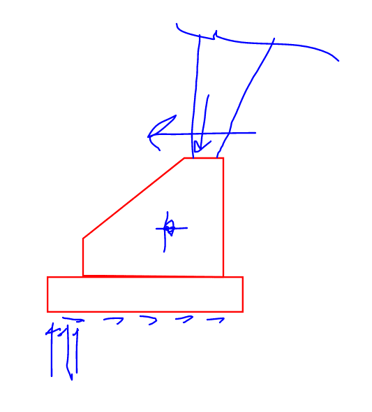
Given the scale of what you're doing, combined with the not having tension piles as an option, I kind of feel as though your heading in the direction of a gravity/buttress wall as shown below. Obviously, that's not going to help your client's blood pressure situation.

C01_k6pmar.png
 
Thank you for the responses.

The crux of the matter seems to be in the sliding. The overturning seemed tough, but not unreasonable due to the bearing pressure.

I think I have some more reading to do with regard to the soil pressure terminology, I feel like I am not quite understanding them properly. I was mistakenly not considering that the soil on the 'upward' side would still be applying pressure, but now that you have said it I can see how it would be applicable. Like a retaining wall calculation, but you have a retention height difference of zero - The resistance to movement of the soil applies, but the soil pressure from the other side(I have used equivalent fluid density before) applies too.

The shear key is a useful idea, i will think about that, but I will need the geotech input for that.

The buttress is a good idea too, the moment forces within my vertical concrete members and footing are quite high. I will probably need to use something like that.

The geo report says we can use an end bearing cast-in-place pile, no mention of requiring casing of the pile shaft. I've never seen the drilling myself, but I understand there is a special auger that can drill and then clear the bottom of the hole (typically a belled bottom). I was wondering if it could be applied as a 'batter pile', if I've used the term correctly. I mean a pile that would be drilled down and to the left in Kootk's sketch and resist the slide with end-bearing of the pile. I'm not a huge fan of 'weird' stuff, so I wouldn't be presenting that idea to a client without a lot more thought.

Regards,

Connor

 
I usually use grade beams for this, but since you can't...if you can use piles, I agree with the use of a batter pile. Though I'd have more than one pile; just one for the batter on each column and the others for uplift/downward forces. You'd need at least 3 piles for stability, so I'd just add one more as a batter pile designed for the horizontal component.

Another idea is to engage the slab-on-grade for sliding. Make it thicker at the moment frame and run some rebar across. It'll be like a wide, shallow grade beam. The only reason I'm not gung-ho about this approach is because it won't have expansion joints, but you could always add some control joints.

Edit: I'd also challenge the assertion that some movement is needed to engage passive pressure. That's generally true, but the soil is quite stiff and has gravel, so I'd talk to the geotech about that. Maybe a shear key would work.
 
milkshakelake said:
Edit: I'd also challenge the assertion that some movement is needed to engage passive pressure.

The best that I can do by way of generic estimation of the required movement is shown below from California DOT's Trenching & Shoring Manual. I'm not really sur how this would translate to a shear key.

If passive resistance is to be used to permanently support gravity load induced thrust in a long span building structure, I feel that it would at least be prudent to design for some non-zero value of frame spread.

c01_gpu7ol.png


c02_kbzfib.png
 
The geotech is MIA still, unfortunately, so I haven't been able to get any input that way. I used to be a serial phone evader too, so I can hardly blame them.

MilkshakeLake:
The project doesn't have an interior slab, which is part of why I have been receiving push-back on cross-ties. It is a horse-riding arena, I haven't been given any information on it, but the client is wary of doing anything that could impact the interior surface quality. I've proposed to do cross-ties but significantly lower than usual (2ft clear above them to grade). I agree this is the best option, but until I have comparable designs the client is immovable. The issue is financial stubbornness due to someone else sizing them a foundation based on the vertical loads only, and their build was fixed price based on that information. Unfortunately, I feel somewhat obligated to make sure the thing doesn't fall over.

Kootk:
I agree it will be necessary to allow for some movement in the design. I will specify a 1 inch tolerance, which I believe allows me to use 60-80% of the passive pressure, assuming medium density non-cohesive soil and depending on the ultimate depth of my foundation (34kN/m[sup]2[/sup]/m to 45kN/m[sup]2[/sup]/m) : based on Rankine method, density 120lb/ft[sup]3[/sup], and 30 degree friction angle). The Clough table is similar to information I have uncovered.

If I use the full passive pressure, as calculated above, the result does not seem unreasonable. I get 5.25ft x 8ft x 14in footing, with bottom of footing at 6.5 ft deep. Delta of 1.5 inches, which is not great and needs attention. I will have to re-build my formulas to account for the maximum deflection and active / at-rest pressures, and adjust the amount of the connected grade beam I am using to resist lateral movement. I am also still assuming a footing reaction in the middle-third of the footing in this calculation, so I may be able to shrink it further if I 'allow the heel to lift' so-to-speak - sliding is still the peak issue though, so maybe not. Then on to the work of making the concrete survive all this.

Thank you all for the input. This forum is invaluable.

Regards,

Connor

 
@ConnorM I try not to misinterpret things, but I believe what KootK was saying is more about a displacement causing additional moments and forces in your structure. Kind of like Hooke's law where F=kx and x is some non-zero number and k is the stiffness of your moment frame.
 
Status
Not open for further replies.

Part and Inventory Search

Sponsor