Continue to Site

Eng-Tips is the largest engineering community on the Internet

Intelligent Work Forums for Engineering Professionals

  • Congratulations IFRs on being selected by the Eng-Tips community for having the most helpful posts in the forums last week. Way to Go!

Overturning Load Anchor Bolt Hand Calcs

jStadts

Structural
Feb 5, 2025
6
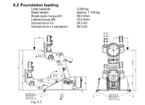
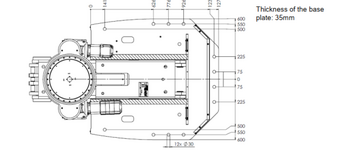
I have a project where overturning is a concern and am confused on how to get the "actual" tension in the anchor bolts that are being proposed. I understand the work flow through ACI on how to solve for the required strengths on concrete breakout and side face blowout etc. A lot of resources are based on a column baseplate with an even pattern of anchors and a centralized moment but my moment is from overturning where it is located at the left end of the baseplate. How do I go about solving for the actual tension on the bolts? The more specific issue is how would I solve for the minimum amount of anchors required to hold the machine down safely.

I've used Hilti Profis to get a general idea but I want to be able to verify via hand calcs.
 

Attachments

  • Screenshot 2025-02-28 100732.png
    Screenshot 2025-02-28 100732.png
    270.2 KB · Views: 21
  • Screenshot 2025-02-28 100800.png
    Screenshot 2025-02-28 100800.png
    110.7 KB · Views: 22
Replies continue below

Recommended for you

If you have a circular pattern of bolts, the derivation of the bolt group moment of inertia is the SUM(Ad^2) where A is the individual bolt diameter and d is the distance from the bolt center to the neutral axis. Add up all these Ad^2 values for the bolts and you have a rough value of Ix for the group.

The bolt group area is the summation of the individual bolt areas of course.

Then take your axial load on the bolt group and the applied moment and use:
P/A +/- My/I to derive the maximum stress at the outer bolts where "y" is the distance to the center of the outer bolt.

This gets you a stress on that outer bolt and by multiplying it by the bolt area gets you the load on the bolt.

There will be, of course, several load combinations to check.
Wouldn't P/A be kN/m^2 and then My/l be kN/m?

P= 49.5kN
A= 1.53m^2

M= 56kNm
y= 1.25m
l= .31 m^3

Obviously don't need you to run through the numbers but just using units I'm still a little confused. Is it A*(d^2) or (A*d)^2? I guess the latter would work out unit wise.
 
I guess in addition that that, I took the neutral axis at the left edge of the plate. Is that correct? Or is there something I have to do to move the moment from the left edge to the center of the plate?
 

Part and Inventory Search

Sponsor