Hi.
I have looked into many P&IDs, list of symbols etc. Haven't found what I was thinking of (maybe wrong, trivial, too basic, who knows![[shadeshappy]](/data/assets/smilies/shadeshappy.gif "[shadeshappy] [shadeshappy]") ), besides I'm a little confused about some things.
), besides I'm a little confused about some things.
Well here it is the, kind of, P&ID of DHW production(please notice that I omitted many essential parts as safety relief valves, check valves, expansion tank etc. since I wanted just to focus to the representation of the basic controls on a P&ID, omitting also piping labels etc.):
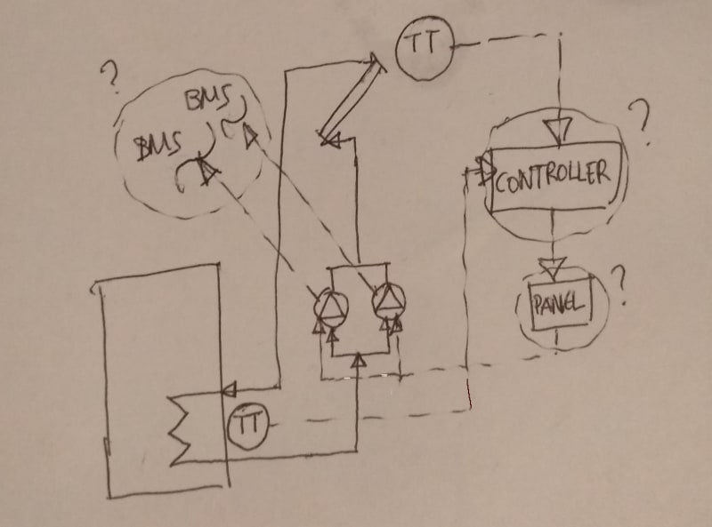
A controller looks into the difference of temperature between the solar liquid at the top of the collector and the low part of the boiler.
If this ΔΤ is above some value (e.g 5oC) the controller sends the signal for the circulation to start in order for the solar liquid to deliver heat to water through the immersed coil. The two circulator pumps are similar and work as 1+1, but not factory made. So they have an external control panel (which alternate the on-duty pump etc.).
Besides, since they are of the smartest kind of nowadays circulators they have the possibility each one separately to communicate via MODBUS with the BMS (sending status, temperature, flow etc.) and of course we don't wanna miss that.
I tried to represent all this the way you see it above.
Not sure for the symbol of the controller(PLC(?)), not sure for the need to show the panel since almost everywhere I saw the signal just being sent directly to the pump(motor), which may be sometimes true but not in this case I think. Also not sure whether communication with BMS is to be shown like this. And last question the PT element for mesuring temperature is just a sensor (noted as TE) or includes a trasmitter(noted as TT) to send the electric signal to the controller itself?
I have looked into many P&IDs, list of symbols etc. Haven't found what I was thinking of (maybe wrong, trivial, too basic, who knows
), besides I'm a little confused about some things.Well here it is the, kind of, P&ID of DHW production(please notice that I omitted many essential parts as safety relief valves, check valves, expansion tank etc. since I wanted just to focus to the representation of the basic controls on a P&ID, omitting also piping labels etc.):
A controller looks into the difference of temperature between the solar liquid at the top of the collector and the low part of the boiler.
If this ΔΤ is above some value (e.g 5oC) the controller sends the signal for the circulation to start in order for the solar liquid to deliver heat to water through the immersed coil. The two circulator pumps are similar and work as 1+1, but not factory made. So they have an external control panel (which alternate the on-duty pump etc.).
Besides, since they are of the smartest kind of nowadays circulators
they have the possibility each one separately to communicate via MODBUS with the BMS (sending status, temperature, flow etc.) and of course we don't wanna miss that. I tried to represent all this the way you see it above.
Not sure for the symbol of the controller(PLC(?)), not sure for the need to show the panel since almost everywhere I saw the signal just being sent directly to the pump(motor), which may be sometimes true but not in this case I think. Also not sure whether communication with BMS is to be shown like this. And last question the PT element for mesuring temperature is just a sensor (noted as TE) or includes a trasmitter(noted as TT) to send the electric signal to the controller itself?