Zachary Jackson
Student
- Feb 12, 2023
- 1
I need to create a diagram of a particular fluid flow system (for a full documented report). I've settled on P&ID as the methodology of choice for the diagram.
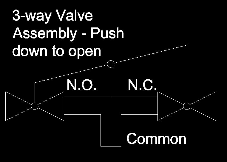
One part of the system is proving difficult to represent: a sort of "3-way valve" that is actually a pair of 2-way gate valves, a tee, some pipe connecting the tee with the two valves, and a lever that operates both valves at once. If one pulls down the lever handle, the right valve opens and the left valve closes. Here's a rough visual representation:
Should I represent it as a 3-way valve, or is there some way to indicate in P&ID that a pair of 2-way valves are... "inversely coupled", perhaps is the term?
One part of the system is proving difficult to represent: a sort of "3-way valve" that is actually a pair of 2-way gate valves, a tee, some pipe connecting the tee with the two valves, and a lever that operates both valves at once. If one pulls down the lever handle, the right valve opens and the left valve closes. Here's a rough visual representation:
Code:
    fixed pivot
         ↓
   +-----O-----+------- ← lever
   |     ∥     |
  =X====>×<====X=
   ↑     ↑     ↑
 valve  tee  valve
Should I represent it as a 3-way valve, or is there some way to indicate in P&ID that a pair of 2-way valves are... "inversely coupled", perhaps is the term?

