Eng-Tips is the largest engineering community on the Internet

Intelligent Work Forums for Engineering Professionals

  • Congratulations waross on being selected by the Tek-Tips community for having the most helpful posts in the forums last week. Way to Go!

P&ID XC Symbol - when and how to use

Status
Not open for further replies.

RicoB

Chemical
Aug 14, 2015
12
0
0
CA
Hello all

I recently joint a new company and I try to get my head around their P&ID, especially their control symbols. I have seen in their P&ID the square with diamond and XC inside. For example :
PT-XC-PCV_afkina.jpg


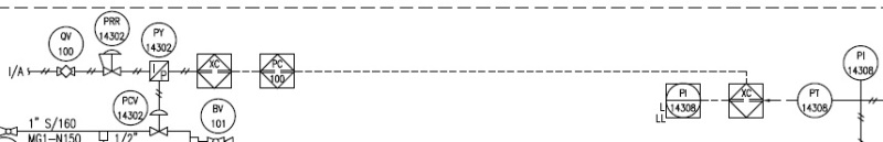
Could someone please explain me how and when to use the XC symbol?
I am also confused about the PC symbol what means PC symbol. I assume it stands for Plant Control but isn't the square with circle and midle line already saying it is in the PC?

Thanks a lot.
R.
 
Replies continue below

Recommended for you

Nobody out here can give you an answer that is 100% accurate. Because we do not have access to the tool you need and should be asking about and searching for. This tool is the "P&ID Legend Sheet". It has all the answers to your questions.

I do not know the name of your Company or where you are located but I am willing to bet your Company created and uses the Legend concept. I am also sure the Client for "this" project has demanded the Legend Sheet.


Sometimes its possible to do all the right things and still get bad results
 
RicoB,

If you Google ISA 5.1 and download the PDF, or otherwise obtain a copy of it, it will help you get started with understanding the basic intent of P&ID instrumentation symbology.

In your graphic, I think "PC" might refer to the Plant (process) Control, but it might refer to "Pressure Control" as well. It looks as though, in this case, that the primary process control for PCV-14302 is a local pneumatic signal that can be over-ridden by the signal from PT-14308. The XC might be a dedicated safety control system that is separate from the plant process control system. (I don't know the SIL classification of the plant...). It looks to me that the intent is to take over control of PCV-14302 on falling pressure at PT-14308, hence the "L" and "LL" low alarm and low low shutdown designations at PI-14308.

My experience has been that if you have 5 P&ID Instrument & Control guys (gals) draw something for the same control loop, you will end up with a control loop drawn 5 different ways; none of them will be in strict accordance with ISA 5.1; and they'll all proclaim themselves to be right. Each place of employment or even each individual project team has its own flavour of poetic license, so it will always be a little frustrating to try and ge the true meaning of these things without talking to the individual who drew it.
 
If my guess - and it is indeed a guess - is correct above, I am also inclined to show a low select (might be high select depending on logic and programming) symbol at PY-14302.
 
I would guess that the air line coming in from the left to PY-14302 is the air supply to the I/P, not a signal (and therefore no high select logic).

And my guess on what the XC's are, a complete guess: They represent the actual I/O point and the dashed lines, "---------", are incorrect. If the XC and the PC are in the same system (PLC, DCS or other), the correct line representation would be ---0---0---0---0---0---

______________________________________________________________________________
This is normally the space where people post something insightful.
 
Hello Everybody

First of all thanks to all of you for taking the time to comment on this. I really appreciate this!
I finally found out a couple thing.

- XC is use as input and output in the panel and it converts the signal from electric to data. So the dashed line in-between the XC's actually has to be a dashed-dot line,
- The square with the diamond and the PC inside, is used as a logic controller in the panel,
- The pneumatic line from XC to I/P should be an electric line (dashed),

I can now see a kind of a systematic but I am still not convinced it is the proper way to do it.

Thanks
Rico
 
This thread illustrates the frustration I have had for over 33 years in trying to get one - and only one - way to represent instrumentation control logic on P&IDs. Not even ISA is fool-proof - most people I have come across tend to "take it under advisement" and go do their own thing. In the OP's example, even when they did *that*, they got it wrong, apparently.

Quoting the OP's latest response: "The pneumatic line from XC to I/P should be an electric line (dashed),"

The fact that it was shown as pneumatic fed into my confusion regarding whether or not it would then be appropriate to show a "select" at the I/P, as the sketch was ambiguous as to which direction the signals are intended to be going.

I think I'll be retired by the time such points of ambiguity are finally addressed in industry in a way that we can all agree on.
 
Status
Not open for further replies.
Back
Top