Eng-Tips is the largest engineering community on the Internet

Intelligent Work Forums for Engineering Professionals

  • Congratulations waross on being selected by the Tek-Tips community for having the most helpful posts in the forums last week. Way to Go!

Pad Mount Transformer Precast Pad Seismic Anchorage 3

Status
Not open for further replies.

driftLimiter

Structural
Aug 28, 2014
1,320
0
36
US
Hey engineers,

Hoping to find someone with more experience in this to help with my understanding.

We have a transformer roughly specified by the electrical engineer on his drawings. The transformer and pad are both utility provided, but the plan reviewer (AHJ) is requiring a structural calc and detail for the unit and pad.

Normally I'd say great let me have the cut sheet and just continue with my calcs. This is a reasonably high seismic area, overturning and sliding aught to be resisted by the anchorage (thats my normal approach anyway).

In this case, the utility wont provide specific information until the AHJ approves the design, and the AHJ wont approve the design without specific information. So its been left to me to skate between them and document something to get the ball rolling.

The Specifics....
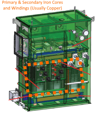
I have a rough idea of the size of the transformer, and its weight. Also there is a typical precast pad provided to attach the deal.
But when I inspect the information things start getting stranger.
Screenshot_2023-10-31_152236_r4xlmq.png


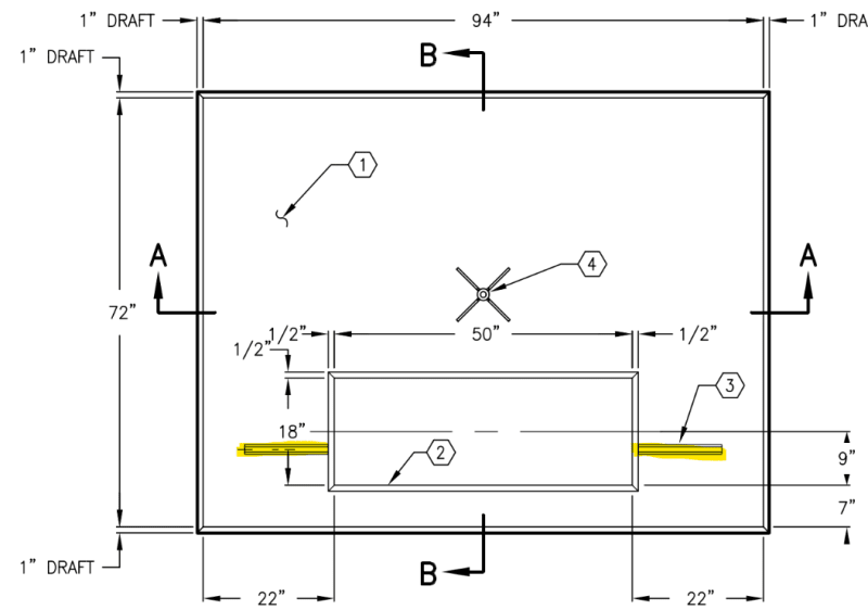
Item 3 I highlighted is the location where the utility says the anchorage will go.
The transformer manufactures are affectionately calling this 'cabinet security anchorage'.

Hard for me to see how this single line of fasteners is going to be useful to resist any seismic overturning.
Which leads me to think that these units don't have a major tipping concern due to seismic. I.e. the CG is perhaps quite low to the ground.


Some major questions are:
1.) Does the utility normally provide a seismic review of the equipment the supply? I imagine they are concerned with seismic in general I don't know how they could not be.
2.) As far as I can tell the anchorage channel is just a unistrut cast in by the precasters, where can I attempt to find strength values for anchorage into these channels?
3.) Does anyone have a feel for the relative CG height of a three phase pad mounted liquid filled transformer? Approx weight is 5000#.

I've been spinning my wheels on this for a while and its still just muddy. One idea we had was to simply make some assumptions and design a cast in place solution, then let the utility come later and submit something different. Perhaps then we will have more specific info on the transformer and can asses the anchorage. Even still I have my doubts that this precast pad arrangement is capable of resisting much overturning load at all because there is only 1 line of fasteners.

Thanks in advance.
DriftLimiter
 
Replies continue below

Recommended for you

In my experience most major utilities have their own design criteria. For seismic, this if often some hodge-podge ELF procedure based on ASCE 7 and/or IEEE 693, or something completely arbitrary. Typical when using this criteria in moderate to high seismic regions the weight of the unit is not sufficient to deal with overturning and anchorage is required. Most of these transformers have an oil reservoir that is supported up high, which I'm not seeing in your snapshot, but this obviously pushes the C.G. up, and usually one side of the transformer base is significantly narrower than the other.

Anyhow, I would be expecting anchorage in a high seismic region. Item 3 surely can't be the anchorage location, this may be the jacking pad?
 
Item 3 in the sketch I showed (which is a plan view of the precast pad) is indicated as "Hold-down brackets".

I'm getting about 50% of the weight as base shear. Assuming a rigid structure and Ch 15 requirements. If I go down the Ch 13 route its basically coming to the same 50%.
A quick check of the footing using the precast pad the utility recommends gives about 6000 psf bearing pressure.
This is assuming Cg = 2/3 * H unit.

Anchorage reaction assuming corner anchorage would be on the order of 1600 # per anchor (overstrength level). If I try to resolve a couple to two anchors in that 'Hold Down bracket' the load will be significantly greater.

All this is pointing me to conclude that there is no way this precast pad is going to work for seismic at this site.

What scares me is that the utility directly indicates that this precast pad is what they would use for this site.

I guess I'm going to go down the route of designing my own pad and anchorage...

Do you know if I can spec some kind of bracket to add onto the transformer base to accommodate the anchorage?

Im envisioning an angle that is welded onto the transformer. Perhaps I indicate some minimums to the transformer provider...
 
driftLimiter said:
1) This is assuming Cg = 2/3 * H unit.

2) All this is pointing me to conclude that there is no way this precast pad is going to work for seismic at this site. What scares me is that the utility directly indicates that this precast pad is what they would use for this site.

3) Im envisioning an angle that is welded onto the transformer. Perhaps I indicate some minimums to the transformer provider...

1) Cg = 1/3*H unit, is more likely. Most of a transformer's weight, say 70 to 80%, are the iron core and the wire (usually copper) windings on the core for primary and secondary circuits. In a pad mounted transformer the core / windings are "low", so that hot oil will flow upward by natural convection where it is cooled then recirculates back down to the core. Core & windings surrounded by dotted orange line in this image (ignore the red lines)

Pad-Mount-400_lncjsd.png


2) Not surprising, for the design earthquake you are likely using. Economics for an electric utility are different for the distribution system. "Quick" and "Cheap" are more important than "Good". Pad transformers are used in large numbers, it's more important for the utility to get it placed and in service than to have robust construction. Anyway, an earthquake that displaced a typical pad mounted transformer would be the least of the utility's problems... the entire distribution system would probably be trashed.

3) This defeats the purpose of a pad mounted transformer... see above (Quick & Cheap). Most USA states exempt utilities from building codes, that's why utilities have their own standards: To address the economics that applies to their business.
 
Thanks each of you for the useful replies.

The way I am currently seeing this is that the AHJ for the building structure is not the same as the AHJ for this isolated equipment (the Utility provider).
And that really the plan reviewer has over-stepped and is putting me right in the middle of a much bigger issue.

I am going to try to see if the plan reviewer can point me to where in the code this equipment is covered and where the design requirements for seismic are indicated. (I don't think they are there at all)

Don't really know what else to do here other than spec out a massive foundation and anchorage elements. Which potentially is just kicking the can down the road because the utility will just say they want to use precast pad per their standard anyway.

 
If the utility does not have their own internal design criteria, I would do as you have done and go down the CH 15 route and design the foundation/anchorage accordingly. Typically there is a base skid that would be used for points of anchorage.

I would not agree that a toppled over transformer would be the least of their concern. The lead time and cost for these is significant, and hopefully there would be a robust secondary containment system in place as well.
 
What’s the seismic design category? I’d think this would fall into Chapter 13, in which case there may be some exemptions that could come into play depending on SDC.
 
Its in SDC D there's no outs.

bones206 said:
I’d think this would fall into Chapter 13

I've taken this approach most of my career for this type of stuff. But I read another post on here about someone making the argument that it should be Ch. 15.
After carefully reading the intro to Ch. 13 I've come around to agree that this is Ch 15 territory.
Specifically because of language in Ch 13 about being attached to structures, and weighing less than 25% of the seismic mass of the 'structure'.
Hard for me to rationalize that a transformer sitting alone on a precast pad meets those qualifiers.

If you consider the thing to be rigid you can use 15.4.2 and essentially you end up with PGA * Ie. Its very close to Fp min from Ch. 13. So I decided it doesn't really matter which approach you use. Although Ch 15 allows for some benefits in the foundation design that are more of a stretch to apply with Ch 13.

An update on the design....
I made a stupid mistake and applied the vertical load at the corner of the precast pad. Resulting in massive bearing pressure.
When I came back to it I immediately saw what I did, corrected it and as it turns out the precast pad size that the utility uses should be fine.

The only caveat is that I need additional anchorage ideally at each corner rather than that single line of anchors into the channel.
 
I think the 25% rule is intended for situations where there is a dynamic interaction of the component and the supporting structure, since the component mass has a greater influence on the supporting structure response. In your case, it makes sense that you end up without any dynamic amplification, since there really is no supporting structure to interact with; just one rigid mass attached to another rigid mass.

My guess is the single line of anchorage is part of a standard pad design that only works when there is no net overturning moment. It meets the code requirements for positive attachment and resists the seismic shear without relying on friction. Although it can be argued that the Unistrut nuts are relying on friction for seismic parallel to the slots, I would still consider it positively attached and meet the code intent. Should be able to get a typical Unistrut channel bolt/nut capacity from their engineering catalog. The embedded channels themselves only have published load ratings for out-of-plane loads, which you won't care about if there is no overturning.
 
bones206 said:
I think the 25% rule is intended for situations where there is a dynamic interaction of the component and the supporting structure

Agreed but the language of 13.1.1 is highly suggestive that the component is anchored to a structure that is being designed per Ch 12.

I think Ch 15 is more justifiable by the letter, but the difference is basically a wash. As long as you use the rigid section 15.4.2
 
driftLimiter said:
We have a transformer roughly specified by the electrical engineer on his drawings.
Approx weight is 5000#

Since approximate weight is known, did the EE provide the transformer's electrical KVA rating?
That info can be used to narrow down needed action possibilities.

 
@SRE Yes we got it down to a 500KVA transformer and the weight and size are estimated. I took your advice and based my calcs off a CG that is 50% of the height.

Everything is feeling pretty good to me except that single line of fasteners. I'm hoping they can get me a transformer with anchors in all four corners or close to that.
 
Very good, three-phase, 500 KVA pad transformer, that weighs about 5000 lb, and can use a 72" x 94" precast concrete pad with a 50" x 18" opening:

This Eaton 500 KVA transformer comes close to meeting those specs, at least to give you a reasonable basis for preliminary calcs... until the EE delivers the appropriate info.

Also, here is more detailed drawing for a typical 72" x 94" pad, with 50" x 18" opening.

Note on page 2 that "Special Designs" includes "Seismic Applications". Consider asking about that.

 
My mistake, I missed that this was a distribution transformer and was only 5000#. I used to do a lot of substation transformer foundations, which is more critical - usually 100-200 times heavier and thousands of gallons of oil, so that's where my mind went.

We would always use CH 15 vs CH 13 for the same reason you mention above regarding 25% seismic mass.
 
driftLimiter said:
Agreed but the language of 13.1.1 is highly suggestive that the component is anchored to a structure that is being designed per Ch 12.

I think Ch 15 is more justifiable by the letter, but the difference is basically a wash. As long as you use the rigid section 15.4.2

I just looked at the introductory paragraphs for Ch. 13 and Ch. 15. It does appear that the equipment being supported by a structure (Ch. 13) vs. on grade (Ch. 15) is a distinction that determines which procedure to follow. I never would have thought a transformer would be classified as a "nonbuilding structure" rather than an "electrical component" for code purposes, but it does seem to be classified differently depending on how it's supported. It's even more confusing when the word "transformer" is mentioned several times within Ch. 13, but nowhere else in the code. Anyways, thanks for enlightening me!
 
@Bones206 I'm with you. Its unfortunate that Ch 13 has specific values for R for "Electrical Transformers" while Ch 15 your left with Non-building structure not similar to building - other. Lol.

Also rigid structure assumption is rather problematic because it indicates specifically the period less than 0.06s. Since you aren't getting that info from the transformer MFGS were left with judgement.

As a note, I looked at the base shear using Sds / R /Ie and the using the 'Other' R factor from Ch 15 and man o man. It came out to over 100% the weight.

To me the only reasonable approach is the 15.4.2 because it is essentially the PGA and that makes the most since to me.

 
Status
Not open for further replies.
Back
Top