Eng-Tips is the largest engineering community on the Internet

Intelligent Work Forums for Engineering Professionals

Parallel 15kV Feeders

Status
Not open for further replies.

lyla1711

Electrical
Jul 8, 2020
13
0
1
US
We have a situation where we are planning to parallel conductors of different length and characteristics.

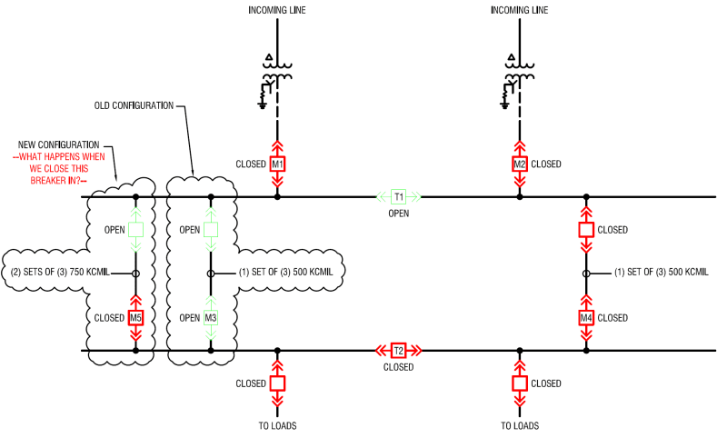
We have a 15kV M-T-M switchgear with paralleled transformers (automatic tap changer controls fully commissioned for paralleling), but the gear is run with the tie normally open. This gear feeds a downstream M-T-M gear which is also run with the tie normally open. We're doing a capacity upgrade on the feeders. In order to cut-in the new feeder, we will be closing the downstream tie, opening one of the old feeders (500 MCM, 1000'), and closing in one of the new feeders (2-750 MCM, 700'). We will then open the downstream tie.

My question is this: what happens when we parallel these 15kV feeders with different characteristics? I believe it will be a simple current divider (the larger feeder will see more current than the smaller feeder), but I need a sanity check.

PAR_FDRS_umzyky.png
 
Replies continue below

Recommended for you

Sorry I did not follow all of this, but in general it will be a current divider.

Some on your protection, if you have a switching fault.

And don't forget on feeders, small impedance can add up. Cables, breakers, splices, etc.

 
Right - so we will see the majority of the current flow through the (2) sets of 750s, but we won't see any objectionable circulating current or reverse power flow or anything strange like that..... Right?
 
What's your governing code? In the US, if you're under the NEC, no you can't; but if you're under the NESC you can, but you'll need to run the load flow studies that show you won't overload either feeder.

I’ll see your silver lining and raise you two black clouds. - Protection Operations
 
This is an NESC application. The load on either feeder is fine for the cable size and 51/50 relay settings. The system is redundant so that either feeder can handle the entire present day load of the plant should one side have an outage.
 
Hope the OLTCs re synchronised using AVRs and maintain same tap all the time. If there is a problem in tap changers, there will be alarm to the operator.
Hope the distance between two switchboards is not much to be a concern with regard to circulating currents as the to transformers are proposed to be effectively paralleled at the downstream switchboard.
If the paralleling is for short duration, it should be fine. If not, protection system also will need to be looked in to as an uncleared fault in one of the outgoing feeders of downstream board could knockout both the incomers (as these are not meant to be paralleled originally, expect the incomer protections to be identical and no protection at Bus coupler). The same applies in case of bus fault in the downstream switchboard as well.
 
The transformers have tapchanger controllers (beckwith m-2001d) which use the circulating current method. They're always within one tap position of each other, and we do have an off-tap alarms being monitored.

The feeder length on one side is about 1000' and it's 750' on the other side.

The two sides will be in parallel for a few seconds and then the downstream tie breaker will be opened.
 
The other method is if you know the impedance difference and can calculate the taps where the circulating current is lowest, just take the LTC off automatic, and set then where you need for the short time.
 
I probably do have enough information to perform those calcs. I do struggle with the idea of circulating current - what is physically happening. Are you aware of any good explanations of this?
 
If the two transformers have different ratios one will produce vars and the other will absorb vars. The vars will flow from the producer to the absorber on the 15kV side and then from the absorber to the producer on the high-side.

I’ll see your silver lining and raise you two black clouds. - Protection Operations
 
Check out Beckwith application notes 11 and 13 for examples of how to do the circulating current calculations.

Typically Beckwith 2001Ds would run in independent mode if the bus tie (T1) is open. With 100% of the load currently on M2 and 0% load on M1, the banks cannot have the same voltage and the same tap position unless the load is quite small. If the paralleling scheme was installed per Beckwith's default guidance, the transformers would presently have the same voltage but the bank feeding M2 would be multiple steps higher. Can you check whether the off tap alarm actually works with T1 open?

Typically we put LTCs in manual prior to making/breaking a paralleling situation. If the banks are very heavily loaded, matching tap positions prior to closing would mean a unacceptably large voltage difference between the banks prior to closing. We typically adjust the LTCs to a reasonable compromise between matching tap position and matching voltage. With very heavy loads sometimes circulating current after paralleling will exceed the limit inside the 2001D, necessitating moving the LTC via the manual control.

The coordination between transformer breakers, bus tie breakers, and feeder breakers changes dramatically when switching between radial and parallel operation. In addition ensuring faults are cleared in either configuration, consider whether you will try to coordinate for the correct breakers to operate while paralleling. For short duration paralleling, it may be acceptable to overtrip.
 
The sources are fed from different circuits in the same upstream sub, and they always float between the same two taps when the load is split. Additionally, there are other feeder breakers on the upstream bus (the one with T1). The feeder breakers we're discussing represent about half the total load, but even when we put all the load on one side, the taps only get two positions apart.

I'm going to do the beckwith calcs and check the relay settings of the downstream tie (T2). I might close the upstream prior to doing this to make sure the transformers are on the same tap prior to the downstream switching. At the very least I'm going to verify both position and voltage.

The transformers are only loaded to ~half total capacity with the entire load on them (so ~quarter of base rating with load evenly split).

The off tap alarm has been commissioned and is working.
 
Taps on manual for the duration of the switching should be considered de rigueur; adjustment of taps to bring as close to zero as possible the amount of reactive flow through the parallel-breaking device always contributes to smooth switching.

It's also important to ensure the parallel-breaking device has the capability for the task; I've occasionally encountered circumstances where I was glad I asked the question first . . .

You didn't mention phase checks, but I'm pretty sure you're building them into your plan . . . ?

CR

"As iron sharpens iron, so one person sharpens another." [Proverbs 27:17, NIV]
 
Status
Not open for further replies.
Back
Top