Eng-Tips is the largest engineering community on the Internet

Intelligent Work Forums for Engineering Professionals

Paralleling a Single-phase transformer with a three-phase transformer 1

Status
Not open for further replies.

CuriousElectron

Electrical
Jun 24, 2017
182
0
0
US
Greetings,
Can a single-phase transformer be paralleled with a three-phase transformer? Given that the voltage levels are the same, turns ratio is the same, but the kVA ratings are different.
Both units would be feeding a distribution panelboard. Both units would be supplied from the same power supply.
The desire to add a single-phase xmfr is to supply the single phase loads on the panelboard.

Thanks,
EE
 
Replies continue below

Recommended for you

What do you mean with paralleling in this case?

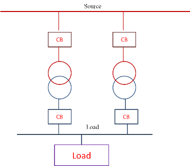
Take into account that paralleling of transformers means that both primary terminals and secondary terminals of the transformers to be paralleled are connected together (primary terminals to the same supply bus and secondary terminals to the same load bus, with corresponding phases), like this:

Parallel-Operation-of-Transformer_zzlvhy.png


If you want to connect two transformers to the same supply, but each transformer load is on different buses, then is not a parallel operation and you can do it without a problem.
 
Maybe yes, maybe no.
It depends.
What is your proposed connection?
Is your secondary delta or wye?
Are your single phase loads line to line or line to neutral.
The %Z is the most important factor.
In all cases, the KVA bases must be normalized to the same %Z.
Example:
A 25 KVA @ 2.5%z transformer is paralleled with a 100 KVA @7.5% transformer.
1) Both transformers normalized to 7.5 %Z;
100% load on the 25 KVA transformer = 33% load on the 100 KVA transformer.
100% load on the 100 KVA transformer = 300% load on the 25 KVA transformer.
Total safe capacity = 58 KVA (25 KVA + 33 KVA)
2) Both transformers are normalized to 2.5 %Z
Similar results, the impedances and the load sharing stays the same, even though the numbers change.
The maximum safe load occurs when the transformer with the lower %Z is 100% loaded.

But you may also wish to consider:
The maximum safe single phase load on a delta secondary is 2/3 of the rated capacity of the three phase bank.
When adding a transformer in parallel with one side of a delta supply, either double the rated KVA or halve the rated %Z
eg: A transformer is to be added to one side of a three phase delta to support single phase loads.
The three phase bank is comprised of three 100 KVA transformers with impedances of 4%Z.
For purposes of determining the maximum safe loading when adding a single phase transformer, consider one side of the delta bank to be a single 200 KVA transformer with an impedance of 4%Z
An interesting note for the purists:
Transformers in parallel will share the load in the inverse proportion to their PU impedances.
In the case of transformers with the same PU impedance but differing X:R ratios, the transformers will share the load equally, but the sum of the KVA loading on each transformer will be more than the KVA of the load.
Explanations:
It is generally overlooked that KVA is a directed value.
KVA is Kilo-Volt-Amps.
Amps are a directed value, hence KVA must be a directed value.
The directed sum of directed values must always be equal or less than the numeric sum of those values.
Why is this not general knowledge?
When adding load KVA values, the actual KVA at the source will be equal or less than the numeric sum of the KVA loads.
The answer will always be safe and conservative.
Also, it doesn't make much difference.
In the case of transformers, it only makes a difference if the transformer circuits loaded to a KVA equal to the sum of the loads under conditions of maximum ambient temperature for an extended period.
If you are testing transformers in parallel and with differing X/R ratios in a lab, you need this information to make sense of your measurements.
In the field, don't worry.


Bill
--------------------
"Why not the best?"
Jimmy Carter
 
Argotier,
Mine setup is similar to yours, except this is a low-voltage configuration.
I've attached a single line of how this setup would look like. I need to supply single phase loads from the single phase transformer, since the three phase unit has a limitation on how much power it can supply to the single loads based on the percentage of its rated kVA. I have an option of feeding each transformer from their own circuit breaker also.
This would be temporary power setup.
Regards,
EE
[URL unfurl="true"]https://res.cloudinary.com/engineering-com/image/upload/v1601665344/tips/Parallel_operation_of_xfmrs_xojnb8.pdf[/url]
 
I had not thought of that possible connection.
Rather than list the possible issues, Please supply the following information:
Transformer KVAs
Transformer % impedance voltages.
Anticipated load.
Several issues go away if you feed 240 Volts to Phases "A"and "C".


Bill
--------------------
"Why not the best?"
Jimmy Carter
 
Waross,
The three-phase unit is rated at 75kVA with 3.4% impedance. The single-phase unit would be rated at 25kVA, standard impedance(don't yet know the % impedance).
The anticipated load would be 13kVA single phase, and 45kVA three phase. The base load would be the single phase load, with a three motor cycling on and off.
I understand there may be some circulating current due to the difference in impedance between the two transformers.
I may elect to not connect the neutral of the three phase transformer to the panel, so that I don't overload it, and just supply the 120V loads off of the 25kVA unit.
Do you see any issues with this setup?
Thanks for all the feedback.
EE
 
Never seen a neutral taken out from the middle of a delta phase, is that something common in ANSI world??

For starters, I can see at least one big problem: you connected the primary of the single phase trx to phases B-C, but then the secondary is connected to N (middle of A-C) and C.

With that connection there will be a voltage angle mismatch, as the single phase transformer secondary will be in phase with its primary voltage B-C, but the corresponding connection from the 3ph transformer is in phase with voltage A-C, 120º apart. The N point should be brought out from the secondary B-C winding or the primary of the 1ph trx connected instead to A-C.

EDIT: Addendum in italic.
 
argotier said:
For starters, I can see at least one big problem: you connected the primary of the single phase trx to phases B-C, but then the secondary is connected to N (middle of A-C) and C.
Good catch.
I missed that.
The primary of the single phase transformer should be fed from A-C
Four wire delta:
Not an uncommon connection in the US.
More common as an open delta with mismatched transformers.
eg: a 100 KVA transformer feeding 120/240 Volt loads and a smaller 5 KVA, 10 KVA or 15 KVA transformer feeding three phase 240 Volt loads.

Bill
--------------------
"Why not the best?"
Jimmy Carter
 
My technical books also state that the maximum single phase load on a delta secondary is 2/3 of the rated capacity of the three phase bank.
However, the transformer nameplate states that the neutral connection only has 5% of KVA rating maximum.
The single phase transformer would be a good contingency to have.
Thanks,
EE
 
Different transformer regulation % may cause circulating currents.
These currents will be low, will be highly reactive and won't cost much in losses.
Different % impedances significantly affect load sharing.

I may elect to not connect the neutral of the three phase transformer to the panel, so that I don't overload it, and just supply the 120V loads off of the 25kVA unit.
25 KVA at 120 Volts = 208 Amps,
That will take a 200 Amp panel and two #3/0 AWG conductors.
25 KVA at 240 Volts = 104 Amps.
That will take a 100 Amp panel and three #3 AWG or #2 AWG conductors.
120 Volt panels at 200 Amps are not available.
The 120 Volt solution will take a 200 Amp panel versus a 100 Amp panel and approximately 3 time the total circular area of conductors.
The 120/240 Volt solution will give the option of connecting 240 Volt loads in the future.
The losses of the 120/240 Volt solution will be less.

Bill
--------------------
"Why not the best?"
Jimmy Carter
 
Dear Mr. CuriousElectron
Q. "....Can a single-phase transformer be paralleled with a three-phase transformer? Given that the voltage levels ..."
A a) The present " Dd n(?) " transformer is an usual practice in the US (?) , but not in the IEC world.
b) It is going to be very complicated with numerous factors to be taken into consideration.
c) strongly agreed with Mr. argotier's learned advice:
" I would supply the single phase loads from the 25 kVA trx directly. It's a simpler solution".
Che Kuan Yau (Singapore)
 
Like David said, add a single phase 240/120V panel for the single phase loads. Leave the three phase loads on the 3-phase.

While some of the paralleling schemes will work, they don't provide very much additional KVA as Waross pointed out and the complexity is a recipe for disaster.
Paralleling the transformers only saves buying a new panel, you will still need two sets of primary and secondary fuses/circuit breakers to protect the transformers and cables per code. The resulting assembly will have less load capability than two panels.

The odds of not getting the phasing and voltage correct are pretty high either in initial install or later when someone maintains ofr changes it. If wiring is not correct (including getting the taps set right)you will be buying a new transformer anyway after one or both them gets smoked.
 
Status
Not open for further replies.
Back
Top