Hello everyone,
I've bumped into a question I couldn't find easily.
I'm designing a sheet metal part and when setting up the parallelism tolerances was asked a question on how much tolerances can the structure accept or how to calculate the accepted tolerance?
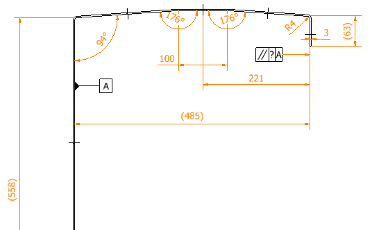
Adding a sheet metal structure for a reference.
Thank you in advance.
I've bumped into a question I couldn't find easily.
I'm designing a sheet metal part and when setting up the parallelism tolerances was asked a question on how much tolerances can the structure accept or how to calculate the accepted tolerance?
Adding a sheet metal structure for a reference.
Thank you in advance.