Continue to Site

Eng-Tips is the largest engineering community on the Internet

Intelligent Work Forums for Engineering Professionals

  • Congratulations KootK on being selected by the Eng-Tips community for having the most helpful posts in the forums last week. Way to Go!

Parapet Wall w/ Overhang 1

Status
Not open for further replies.

Afullilove

Structural
Jul 27, 2023
6
I was wondering what the constructibility would be on something like this in the sketch. I have a concept for a building with a parapet wall at the front which includes an accent overhang of 2-3'. I've seen this look in many modern projects but its usually tied to the main structure of the building. Would this be possible with traditional stick or metal framing? Thanks
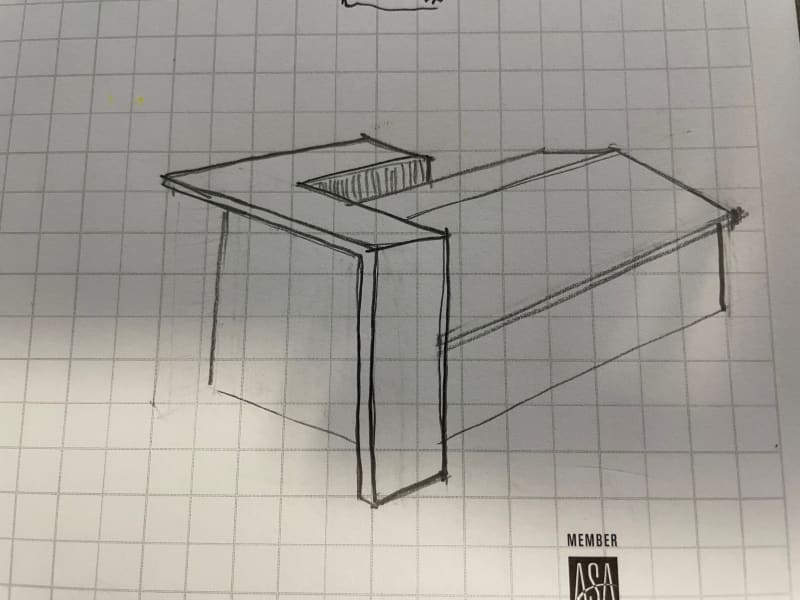
parapet_luyi27.jpg
 
Replies continue below

Recommended for you

Would be difficult. I'd ask from some red iron.
 
Thanks for your replies. Red iron was my first thought. I just wanted to explore any possible alternatives.
 
You may be able to do columns with cantilevered beams at some spacing (6-8'?) and infill with light gauge, but that's about as close as you'll come to stick framing it, I think.
 
Welded light gage might be an option but a much more difficult design.
I'd hold out for the red iron.
 
I do hate welded light gauge. Some people have success with it, but the contractor has to really know what they're doing.
 
I hate all light gage in general :)
When I was doing it, they were able to weld it pretty nicely but I was working with a good crew (Precision Walls)
 
I think it’s possible to stick frame this, although it really depends on your loads and how thin the roof needs to be to meet the desired aesthetic.

There is nothing that I see here that would automatically disqualify wood framing, assuming that’s what you mean by “stick framing.”
 
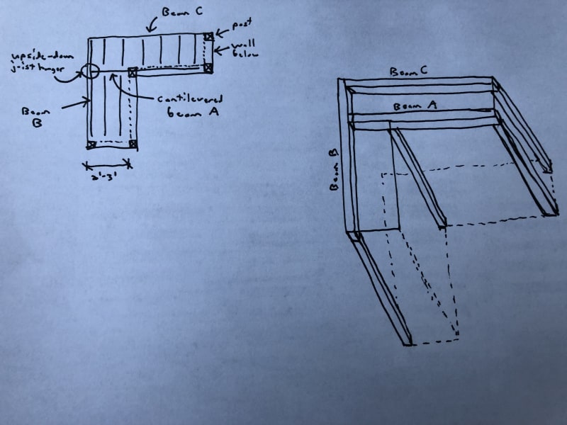
Not sure if it helps but I would probably stick frame it per this bad sketch:
7410B0CF-EFA7-4CCD-AC07-36AE85D78C4F_igxhca.jpg


Beam A cantilevers over post at inside corner. Beam B is supported by Beam A with upside down joist hanger, and Beam B supports left end of Beam C. Not sure best way to run joists. They’re shown running up-down per plan view, but perhaps left-right would be better to resist potential twisting of Beam B considering it’s supported along the inside face.

At the outside corner where Beams B and C meet, I would check the total deflection and make sure it’s reasonable.

Again it really comes down to the loads and geometry in terms of whether or not wood framing works.
 
Fairly easy to design, and can be done. In these environs, you have to very careful with the building envelope and cold transfer for connections.

-----*****-----
So strange to see the singularity approaching while the entire planet is rapidly turning into a hellscape. -John Coates

-Dik
 
@Eng16080 this is exactly what I was looking for. Makes total sense. Thanks for your help.
 
No to rain on anyone's parade, but doesn't Eng16080's schematic have a column in precisely the place most of these sorts of 'modern' designs hate them most?
 
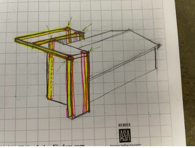
Look at your original sketch. It's all about thin, gravity defying cantilevers. Stick a column on the corner and wrecks the whole aesthetic. I might be misunderstanding Eng16080's sketch, of course, but I'm not sure how else it would be stable (especially if using wood).
 
My sketch is a little wonky and disproportionate and his is sort of a top down isometric, but if I'm understanding his sketch correctly it should be something like this.

Untitled_lcoptl.png
 
Well...there it is. My eyes have been opened!

Though scale will be important. If that's a whole building, I doubt it would work with commonly available lumber/timber sizes. If it's a feature on the corner of a parapet, probably good to go.
 
Those were my initial thoughts as it seemed too thin of a profile to get wood beams to span that far.
 
I agree. Dimensional lumber from the lumber yard is probably not the right choice for this application considering the size.
 
Status
Not open for further replies.

Part and Inventory Search

Sponsor