Continue to Site

Eng-Tips is the largest engineering community on the Internet

Intelligent Work Forums for Engineering Professionals

  • Congratulations SDETERS on being selected by the Eng-Tips community for having the most helpful posts in the forums last week. Way to Go!

Part II - Column 3D Interaction Surface vs Code Biaxial Formulae 4

Status
Not open for further replies.

Trenno

Structural
Feb 5, 2014
831
thread507-460377

What are people's opinions on applying 3D interaction diagrams or codified biaxial for walls?

I'm thinking factors like high aspect ratios, return walls and end bar clusters would skew the results compared to a stocky square column. Essentially the buckling mechanism would be different a "wall" and a "column." 2D element v 1D element.


Replies continue below

Recommended for you

I almost never do bi-axial checks for walls. I usually do an in-plane check and a totally separate out-of-plane check.

Now, if the worst case for each of those checks occurs for the same load combination, then maybe I'd do some sort of simple interaction... Adding up the Demand/ Capacity ratios for the two and making sure it's less than 1.0. But, that's about as far as I'd go.
 
I'd take an approach similar to masonry if looking at the 3D interaction diagram for a wall and build the diagram without allowing compression in the reinforcement, or only allowing compression in bar sets that will be detailed to be tied.

If you start getting into irregular shaped walls with irregular bar layouts then I'd do the 3D curve as in those circumstances a straight-line interaction can be very unconservative for some Mx, My combinations.


My Personal Open Source Structural Applications:

Open Source Structural GitHub Group:
 
Engineering Patrol -

We're talking about walls, not columns. Very different from what was shown in that video.
 
I'm with Josh on this one in that I question whether or not the biaxial column treatment of walls really makes sense given that:

1) The impact of treating in plane and out of plane actions separately is probably pretty minor and;

2) A biaxial treatment including slenderness may be of limited validity given that out of plane flex, and therefore moment amplification, will be very different in the in plane flexural compression zones of the wall than it will be in the interior of the wall panel.

If one has software that makes the biaxial analysis of walls a simple matter, I'd have no beef with using it to design some aspects of the wall so long as some kind of nod were made to the greater stability demand at the boundary elements.

Trenno said:
I'm thinking factors like high aspect ratios, return walls and end bar clusters would skew the results compared to a stocky square column. Essentially the buckling mechanism would be different a "wall" and a "column." 2D element v 1D element.

My feeling exactly. I tend to view most walls having significant in plane flexure as shear panels connecting discrete columns, even when those columns are of the same width as the shear panels. At present, I don't know that anybody really knows how to do a proper "plate in flexure" analysis of a concrete wall. Wight & MacGreggor's textbook takes a stab at it but they are definitely adlibbing, which I totally respect.

C01_rjazsl.jpg
 
Engineering Patrol -

Read the OP's original post again. Understanding how to use column software doesn't really apply to the original topic of this thread. That's all I was trying to say.... Though I could have done it in a more friendly manner. [wink]

What are people's opinions on applying 3D interaction diagrams or codified biaxial for walls?

I'm thinking factors like high aspect ratios, return walls and end bar clusters would skew the results compared to a stocky square column. Essentially the buckling mechanism would be different a "wall" and a "column." 2D element v 1D element.
 
Dr. E. H. Brown said:
Structural Engineering is the art of molding materials we do not wholly understand into shapes we cannot precisely analyse, so as to withstand forces we cannot really assess, in such a way that the community at large has no reason to suspect the extent of our ignorance.

Agree with everything you're saying KootK. I wonder if Agent666 has any thoughts...

I'm trying to think up some tests that can help steer us towards the right answer.


KootK said:
..and therefore moment amplification...
I believe in the ACI if you have a slender wall you have to perform a non-linear second order analysis, so codified moment magnification is out the window.

In my mind the 3D interaction surface would still be applicable but the forces your coming into the diagram with should have full consideration for the slenderness.

If your getting into proportions where lateral torsional buckling starts become a real concern, well then I'm out of my depth and would need to tap my research paper resources to see if I can find anything.

EDIT:
KootK said:
2) A biaxial treatment including slenderness may be of limited validity given that out of plane flex,..
I see what your getting at now. how much different would something like this be as compared to a pre-cast stadium riser in which PCI relies on a general cross section analysis?
Capture_tdz78y.jpg


My Personal Open Source Structural Applications:

Open Source Structural GitHub Group:
 

They're almost the same... I'll see if I can find it, but I wrote a 'knock-off' in Delphi that drew interaction diagrams for columns... and a couple of keystrokes later it was for walls... Used it for a lot of ICF stuff, way back when.

Rather than think climate change and the corona virus as science, think of it as the wrath of God. Feel any better?

-Dik
 
At buildings where your shear walls are on the perimeter, the MWFRS ASCE Wind case that applies 75% of the wind load in both directions could end up controlling the design of the wall with a bending in two directions check.

 
EZBuilding said:
At buildings where your shear walls are on the perimeter, the MWFRS ASCE Wind case that applies 75% of the wind load in both directions could end up controlling the design of the wall with a bending in two directions check.

Let's get back to the original question then. How to do this? Do you use a bi-axial interaction diagram, or do you do some sort of interaction equation using the demand / capacity ratios for the two different directions?


dik said:
They're almost the same... I'll see if I can find it, but I wrote a 'knock-off' in Delphi that drew interaction diagrams for columns... and a couple of keystrokes later it was for walls... Used it for a lot of ICF stuff, way back when.

Well, you can use a general purpose column program to do a "bi-axial" check on a wall. But, how useful is this really? Those interaction equations work great when you've got similar dimensions in both directions. But, does it really make sense for a 10" thick wall that has a length of 50 ft?

What KootK was getting at was the slenderness issue for out of plane walls varies greatly along the length of the wall because one side will be in tension and the other in compression (from the strong axis bending).

Then there's the fact that I typically use on a small percentage of the tension steel for strong axis bending of a wall. Whereas for weak axis bending I tend to check the wall based on a single representative 1 ft length.

What I was suggesting is that we take a simplified approach in our assumptions and either neglect interactions or do a very simple interaction like SA_Demand/Capacity + WA_Demand/Capacity < 1.0.
 
Celt83 said:
I see what your getting at now.

I that I see what you're getting at now. I'd been arbitrarily limiting myself to thinking about single, linear walls with boundary element "stuff". I hadn't been thinking about truly compound wall setups. For such setup, as with the stadium risers, I do believe that biaxial column software has value. Those walls often do have great returns etc that will brace the parts of the wall most likely to suffer from slenderness. One just has to apply some judgment and scan for the bits of walls that are unbraced and may be slenderness critical.

Another wrinkle that affects compound / flanged walls but not columns is shear / tension lag and the issues surrounding effective flange widths.

Some obvious differences between a core wall assembly and a stadium riser:

1) No axial on a stadium riser. Granted, axial is often of minimal significance in a core wall too.

2) Stadium risers will tend to be stocky just by virtue of constructability.

3) Stadium risers are less consequential than core walls in my opinion. That said, I've attended Badger games at camp Randall and was duly terrified: Link
 
JoshPlumSE said:
Let's get back to the original question then. How to do this? Do you use a bi-axial interaction diagram, or do you do some sort of interaction equation using the demand / capacity ratios for the two different directions?

I have utilized an interaction equation with the demand/capacity ratio for both directions.
 
So in ACI 318-08:
Section 14.4 - Walls Designed as compression members
walls subject to axial load or combined flexure and axial load shall be designed as compression members....(goes on to list the flexure and compression member sections, inclusive of deep beam and moment magnification procedures)

Section 21.9.5-Design for Flexure and axial loads (Special Shear Walls and Coupling beams)
walls and portions of such wall subject to combined flexural and axial loads shall be designed in accordance with 10.2 and 10.3 except 10.3.7 and the nonlinear strain requirements of 10.2.2 shall not apply.

Section 21.10.2-Special Pre-cast walls
(kicks back to 21.9)

ACI seems to make it pretty plain that the methods you use to design a column are applicable to a wall for designs under their jurisdiction. My searches in the publication database are coming up pretty dry on the topic.

What I found interesting looking at these sections is in 21.9.5 they indicate 10.3.7 doesn't apply which would seem to indicate two things for special walls
1. phi-Pn,max is not restricted to the minimum eccentricty value
2. Moment magnification is not applicable

My Personal Open Source Structural Applications:

Open Source Structural GitHub Group:
 

actually very... I've done some tall ICF walls using the program.

Rather than think climate change and the corona virus as science, think of it as the wrath of God. Feel any better?

-Dik
 
(These codes are still very foreign to me but I have just started getting into some of them for a cross section tool I have in the works with the open source folks)

CSA A23.3-14:

Appears to also indicate a strain compatibility approach but recognizes that perhaps there should be some requirements for minimum thickness of the wall panels or lateral restraint at the compression block.
14.4.1 - kicks to 10 and 11, in which 10 is the general flexural section
14.4.2.2 low axial compression - gives a wall thickness constraint of Hu/20 for the compression end of the wall with some possible exceptions
14.4.2.3 high axial compression - introduces consideration of slenderness effects if the tension steel doesn't reach yield.

EN 1992-1-1 - Eurocode 2:
9.6.1 - sets a definition on cross-section considered to be walls of length to thickness ratio of 4 and would seem to indicate a strut-and-tie approach for in-plane bending and then slab rules for out-of-plane bending.


My Personal Open Source Structural Applications:

Open Source Structural GitHub Group:
 
Celt83 said:
So in ACI 318-08:

It's worth noting that recent versions of ACI include the hu/16 provision shown below which are, obviously, a nod towards a stability concern for shear wall compression zones.

Celt83 said:
ACI seems to make it pretty plain that the methods you use to design a column are applicable to a wall for designs under their jurisdiction.

I don't share that conclusion. My impression of the code provisions that you listed is that they are simply directing us to use the same strain compatibility assumptions that we are directed to use for beam-column elements of any strife throughout the code. And, while not explicitly stated as such, it is also my suspicion that all of the strong axis flexure wall provision in ACI and CSA are intended to address uniaxial, strong axis flexure.

Has anyone seen an example of a single wall shear wall treated biaxially in any ACI document? I don't recall encountering one.

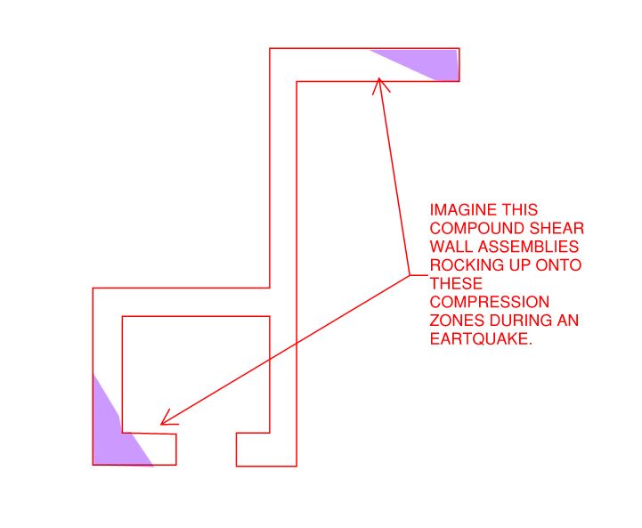
I can only even think of one example of an ACI document suggesting a biaxial treatment for a compound, core wall assembly. And that is shown below. I've no beef with folks using ETABS, S-Concrete etc to do biaxial on such wall assemblies though. That, not because the code tells us we can but, rather, the codes does not tell us that we cant and, obviously, we've got to so something. So, in the absence of clearer direction, that's our something.

Celt83 said:
Section 14.4 - Walls Designed as compression members walls subject to axial load or combined flexure and axial load shall be designed as compression members

There's a wrinkle with this when considering shear walls this way. When a shear wall rocks up onto it's compression zone, we're basically saying that that compression zone forms a chunk of wall over which the full compression strength of the wall is mobilized. In many instances, treating that strip as one would a non-shear wall under uniform compression isn't going to work. It's akin to trying to design a wall loaded to its squash load all over. Fortunately, shear wall compression zones benefit from being forced to buckle in lock step with the portions of the wall that are not so highly stressed as a result of the stress gradient along the wall. I believe that this is why we toss out conventional, slender wall design for shear walls and instead do the hu/16 stuff.

Celt83 said:
What I found interesting looking at these sections is in 21.9.5 they indicate 10.3.7 doesn't apply which would seem to indicate two things for special walls
1. phi-Pn,max is not restricted to the minimum eccentricty value
2. Moment magnification is not applicable

I feel that both of those nuances can be explained by recognizing that a seismic shear wall is predominately a beam, by definition, which implies that:

1) the in-plane eccentricity is already massive by definition (outside of the cross section) and;

2) the in-plane moment magnification of the compression zone is meaningless because it's braced in-plane by the parts of the wall outside of the compression zone.

3) the in-plane moment magnification of the wall in aggregate is dealt with when considering the stability index of the building lateral system as a whole.

Again, in my mind, these things suggest that ACI is speaking to a uniaxial treatment of individual wall segments.

C01_lglxzc.jpg


c02_xy6yy1.jpg
 
By way of a visceral, thought experiment, imagine the situation below which I've had the pleasure of studying in real life. I frankly question the intuition of any engineer who wouldn't vomit in their mouth a little at the prospect of something like this trying to cyclically plastic hinge during an earthquake with lives on the line. This is part of what informs my discomfort when it comes to the "it's just another column" sentiment.

C01_v51506.jpg
 
Status
Not open for further replies.

Part and Inventory Search

Sponsor