Eng-Tips is the largest engineering community on the Internet

Intelligent Work Forums for Engineering Professionals

Partial length collectors on WSP Diaphragm

Status
Not open for further replies.

driftLimiter

Structural
Aug 28, 2014
1,320
0
36
US
I'm working on seismic retrofit for an existing building and would like to investigate possibly using partial length diaphragm boundary nailing in order to reduce/eliminate the need for new full length straps over blocking. This isn't something I normally would try, but since this is retrofit work it will be especially intrusive to add new floor straps and verify boundary nailing. So I thought I'd see what other options I have.

After a quick refresher on Terry Malone's book it seems like the only way he allows for partial length collectors is when using a transfer diaphragm. Perhaps I could use a similar approach but I'm not feeling like it will be particularly successful without ripping apart the existing and adding boundary nailing and straps everywhere.

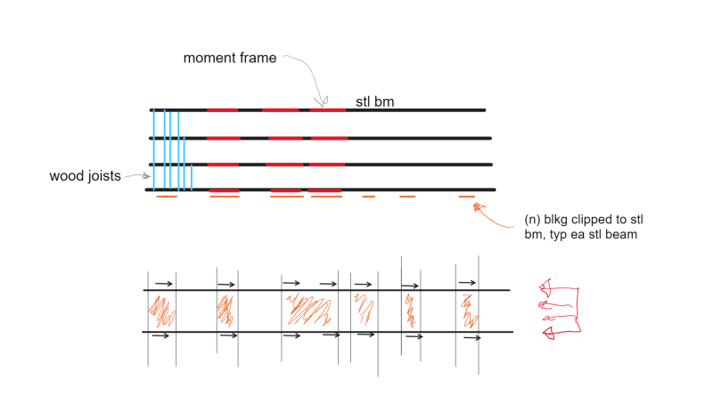
What my goal really is, is to provide minimal new blocking and boundary nailing over existing collectors at some intermittent spacing. I would provide full length blocking and boundary nailing over new lateral frames. Important to note that I have good full length collectors but the existing blocking is not full depth, and the nailing of the WSP to the blocking is unknown.

The concern is that without a full length boundary nailing, the WSP diaphragm needs to resist some tension and compression. And some of that tension has to travel through WSP joints (cross grain bending in wood member below).

Does anyone know of a rational approach to use partial length boundary nailing? The existing floor diaphragm is 1"+ WSP, my biggest concern with tension is the at the joints.
 
Replies continue below

Recommended for you

Partial length collectors has, historically, been the way of it in most regions for most of history. I grant that:

a) things are likely different now in your region and;

b) for very conventional framing layouts, one often winds up getting the transfer diaphragm boundary elements "for free".

This might have to be something that you work out with the building department if they are at all friendly. Establish a collector tensile value below which everyone feels good about getting that done via diaphragm in plane tension and extend the collectors only that far. This probably means that the collectors extend some amount beyond the new VLFRS.

This is a bit similar to how one sometimes approaches the fireproofing of external, post-tensioned concrete reinforcement: a collaborate building department accepts that massively improving a building is a constructive thing to do even if it isn't wholly "by the book".
 
KootK thanks for the quick reply.

So conceptually I would develop a Dragstrut/Collector Force Diagram for the WSP diaphragm itself and compare the peak tension there with the "tensile value below which everyone feels good about..."

I will ponder this a bit and run some numbers. I may opt to use this approach on some new construction as well because I believe that people hate my full length straps over blocking.
 
I've worked out in the Midwest and out in high seismic land.

In the Midwest, we let partial length collectors fly, designing the collector length to be the required length to transfer the force. For example, if I could xfer all diaphragm forces through the shearwall connection, congrats, you just eliminated painful collector detailing and design. We always told ourselves that partial length collectors would not be a thing in high seismic land.

Now, working in high seismic land, partial length collectors are still alive and well. Do I like it? No, but I do it to avoid being "the extreme engineer".

I would try to figure out the length of collector required and design for that length even if partial length.

S&T -
 
With the partial length collector, can you follow the loads all the way through without magic? Show that the stresses can all get to the collector through the diaphragm? Show that the loads don't need to spread out without an identifiable load path somewhere downstream of the collector? Is there enough restraint in all the directions on the diaphragm to make sure there won't be weird twisting issues that might unzip something or put unexpected forces on it? Are you okay with deflection compatibility, or will load end up trying to go somewhere else that isn't what you're officially designating as the collector? If you picture this cycling reversible loads, do you see a potential problem?

If that's all okay, I think you're probably fine for a retrofit if you don't think the cost adds value. I'd point out that I'd done it on the drawings or documents, though. In this case, it's likely not assuming there's not collector at all, but rather assuming some amount of tension capacity in the diaphragm that acts to collect load. In retrofit situations, there are lots of times where it's not reasonable to meet detailing requirements. 'Reasonable' is always a cost-benefit question. Depends on the project and context as to whether this is reasonable in this case.

 
Thanks for the valuable insight thus far.

Perhaps I mislabeled somewhat my post. Let me try to clear it up a bit.

There are a series of steel beams that support a wood deck. The steel beams are continuous or made continuous fairly easily.

I'm going to use the steel beams to deliver load to new LFRS elements.

The existing floor joists are blocked, but they are not all full height, and there appears to be no connection of the blocking to the steel beams, probably no diaphragm nailing to the blocking either.

The diaphragm has all kinds of strength in shear. So what I trying to do is get shear transfer to the steel beams, without having to replace the blocking and add new nailing in each joist bay.

But instead have intermittent shear transfer by only blocking a lesser amount of bays.

Again I've always just done full length collectors with boundary nailing. So this idea is new to me.


Yes, you can use partial length collectors provided you consider all the points TLHS made. You'll need to do it without relying on plywood tension (SDPWS-21 4.2.7.1). You'll essentially be creating a notched diaphragm where the notch length extends from your wall / partial-length collector to the first full length collector (sounds like this will be your steel beam line). The depth of your notched diaphragm will match the depth of your partial-length collector. Ignore the diaphragm outside of this region and make sure you have adequate shear and chord capacity in the transfer diaphragm. If you're able to post a quick sketch of the framing plan we can offer additional guidance.
 
dL said:
The existing floor joists are blocked, but they are not all full height, and there appears to be no connection of the blocking to the steel beams, probably no diaphragm nailing to the blocking either.

In the context of a renovation, that setup actually feels pretty great to me, especially if you swapped the partial height blocking for full height blocking that is clipped to the steel beam somehow. That, even if that blocking is not fastened to the diaphragm.

I'd need to see a plan to better gauge the nature of the horse trade but, in many situations, I feel that I'd prefer the full depth collector without the deck fasteners to an aggressively short partial collector with the deck fasteners.

A properly detailed transfer diaphragm in a retrofit is a pretty big ask in my experience.
 
Deker said:
You'll essentially be creating a notched diaphragm

I believe this is the push in understanding I needed to go ahead and apply a rational diaphragm analysis like in Malone's text.

KootK said:
I feel that I'd prefer the full depth collector without the deck fasteners to an aggressively short partial collector with the deck fasteners.

I'm thinking the WSP always has something to push on and the load becomes tension in the steel beam. I believe this is the notion of what your saying.

Thanks for all the valuable insight !
 
Deker said:
You'll essentially be creating a notched diaphragm where the notch length extends from your wall / partial-length collector to the first full length collector (sounds like this will be your steel beam line).

@dL: take careful note of that highlighted bit. It means that the whole partial diaphragm / notch thing will be bunk if you don't already have an existing, full length collector someplace that runs parallel to your partial collector. Obviously, if you'd have to fix the diaphragm connection at the new, full length collector anyhow, you'd be better off just doing that same exercise at the collector directly aligned with your VLFRS.
 
I think you likely want to sketch out a free body diagram of your forces as they enter the collector and back to a point where you're sure they're reasonably spread out by an element in the diaphragm.. There's a bunch of ways to rationalize that last few feet, you just need to make sure you've actually accounted for all the boundary forces and moments. If you can draw them out, sum them all to zero and prove the capacity you should reasonably okay.

The stuff that tends to sneak up on me with diaphragms is moment effects that seem like they should be insignificant. The extra diagramming step makes it a lot harder to accidentally tell yourself there's a load path when there isn't, or when the induced loads are larger than you'd expect.
 
Attached is a schematic view of the diaphragm problem.

The steel beam collectors are continuous.

The plan is to add new blocking w/ clips over all the moment frames, then spaced out.

I sketched a sample diaphragm region on the bottom of the page.
I'm tempted to take make diaphragm regions (shown orange shaded) that carry their own inertial load + the tributary amount from each side where there are no blocking reactions.

Seems to me if I can get blocking at each end of the building, then spaced intermittently in towards the moment frames then I can avoid any tension.

Would love to hear more thoughts hope this sketch helps understanding of the situation.

null_q5owkc.png
 
Not quite what I was envisioning, but now that I see what you’re doing I think you’ve got the concept. A bit of semantics: this doesn’t appear to be a partial-length collector issue, but rather a shear transfer issue. Your solution still relies on the steel beams to act as full length collectors.

If you were trying to reduce the forces on the collectors and their connections (or eliminate them completely) by concentrating your shear transfer at the frames, that would necessitate partial-length collectors. Based on your comments above, that doesn’t appear to be the issue you’re trying to tackle.

Out of curiosity, does your solution offer any advantage over blocking every 3rd or 4th (or whatever) joist bay along the entire length of the beam?
 
Deker said:
Out of curiosity, does your solution offer any advantage over blocking every 3rd or 4th (or whatever) joist bay along the entire length of the beam?

What I am trying to do is to reduce the shear transfer elements outside the moment frame as much as possible.

If I could just have shear transfer over the moment frames that would be the ideal situation. I'm just having trouble visualizing the loading on the diaphragm regions that are not bounded by shear transfer elements. (the unshaded regions in the bottom part of my sketch).

Like I said earlier my feeling is that if I at least have some shear transfer 'in front' of the diaphragm region then it always has something to push against and doesn't have to drag tension through the diaphragm. But after reading Malone and some of the comments here I am worried this might be an over simplification.

 
In order to have shear transfer over the moment frames only, you'd have to justify a way for all of the diaphragm load to get into your main transfer diaphragm. Perhaps you could rationalize a way that the diaphragm on one side of the frames could strut directly into your main transfer diaphragm, but the diaphragm on the opposite side of the frames (the portion trying to move away from the frames) still has strut into the mini transfer diaphragms and make it's way to the steel beams where it's load is delivered back to the frames via a collector load path. So you're not saving anything over a traditional full-length collector design.

I don't have an issue with what you've shown, but considering what I've written above, uniformly distributed shear transfer elements over the entire length of the collector may net you the same design, and they would be simpler to detail and convey on the drawings.

 
dL said:
If I could just have shear transfer over the moment frames that would be the ideal situation.

If you wanted to localize the attachment as much as possible and you could make the numbers work, you could provide the full depth blocking only locally at the the far ends of the collectors and omit it entirely above the moment frames. As a general principle, one likes to place resistance as near to load source as possible but that is by no means mandatory if you've got good reasons to do otherwise.
 
@koot this is what I ended up with I have a new blocking region at each end that makes up new transfer diaphragms. And another transfer region over the moment frames.

I determined the length of the two outside transfer diaphragms based on the assumed diaphragm strength and assuming that the unblocked regions only react on the transfer regions in 'compression'. Checked my arrangement for EQ loads in either direction, then design the collector and it's splices with only loading coming from the transfer diaphragm regions.

Numbers worked out pretty well and we're happy with the arrangement. I told my boss I did about as much Terry Malone as I could muster lol.

Thanks for the input all very valuable.
 
Status
Not open for further replies.
Back
Top