Continue to Site

Eng-Tips is the largest engineering community on the Internet

Intelligent Work Forums for Engineering Professionals

  • Congratulations waross on being selected by the Eng-Tips community for having the most helpful posts in the forums last week. Way to Go!

Partitioned mesh in 3D issue with seeding in 'z' direction

Status
Not open for further replies.

DrBwts

Mechanical
Nov 4, 2012
297
I would like to partition the centre of a plate with a higher resolution mesh but it seems that the through thickness dimension of both partitions are locked, see pictures.

Seed_1_mmh8db.png


Seed_2_xr0v22.png


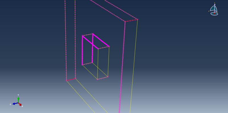
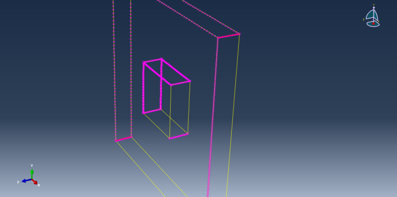
Whenever I try to change the inner partition's through thickness seeds the outer partition's through thickness seeds are automatically updated to match & vice-versa.

Is this a constraint on the meshing that I just have to live with or is there a way around this?
 
Replies continue below

Recommended for you

In a structured mesh you couldn't have a fine through thickness mesh on the inner hole with a coarse mesh on the outer edges, unless you used tet meshing, which isn't advisable. You could reduce the model size by using symmetry, if the boundary conditions and loads permitted, and then use a fine mesh throughout the thickness using brick elements. You should also considering further internal partitions using the faces of the internal hole to give you a better mesh shape overall.

 
Thanks for you reply corus.

I should clear a few things up. The central region is not a hole just a partitioned part of the volume of the plate. Its the area that will be hit by a number of projectiles which is why I want that area to have a higher mesh density.

Would it be possible to mesh the central partition with hex and the outer with tet/hex mixture?
 
Yes. You can assign different mesh methods and element types to your cells. CAE will then give you a warning regarding incompatible meshes and create an tie constraint to connect them.
 
It's not advisable to mix the mesh with hex and tets as Abaqus will impose tied restraints between the regions and cause spurious results at that juncture. You could just use tet meshing but what you find is that the mesh is fine at the seeded edges but quickly changes to a coarse mesh to match the global element size. This can cause some poor element shapes, and overall can be a more expensive model to run with the increase in the number of elements and nodes.
Another way would be to partition the whole region using the internal faces to create 9 cuboid regions (including the centre) and redefine the regions as swept regions. You could then redefine the sweep path to be orthogonal to the original defined path through the thickness. Uncheck the box that says use mapped meshing where appropriate and delete the outer seeded edges that Abaqus created so you only have your internally defined seeded edges. Attached is a picture of a cube where the sweep direction has been changed so that the through thickness edge has 10 divisions on one edge, with 5 divisions on the outer edge. Presumably the technique would work on the 9 regions in your model when combined.

 
 http://files.engineering.com/getfile.aspx?folder=93e5ea2b-c3d3-49aa-aef8-a5b646ca4ce9&file=cubeswept.png
Status
Not open for further replies.

Part and Inventory Search

Sponsor