Eng-Tips is the largest engineering community on the Internet

Intelligent Work Forums for Engineering Professionals

  • Congratulations waross on being selected by the Tek-Tips community for having the most helpful posts in the forums last week. Way to Go!

Partitioning and element shapes option for my geometry 1

Status
Not open for further replies.

mdama

Materials
Oct 12, 2018
118
0
0
GB
Hello
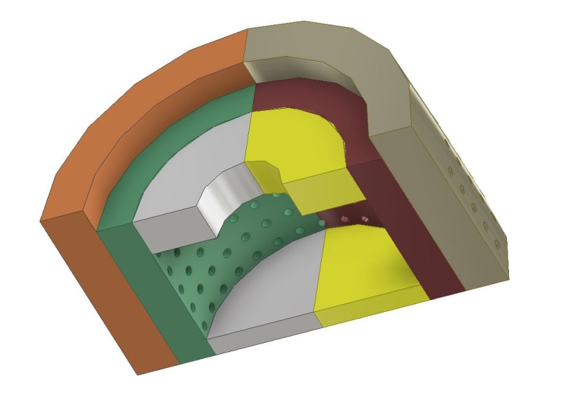
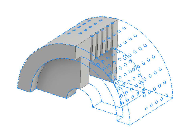
I am working to do a compression test on a geometry as shown here ( ( I use tet shape element so Abaqus comes up with 200,000 elements which is a lot. What is the best way to partition such a structure and what element shapes do you recommend? The geometry length is 15 micron and It has pores in nano size about 250 nm. The problem is the mesh for nanosize pores to get the best accuracy.
Thanks
 
Replies continue below

Recommended for you

Cut those ribs from the cylindrical part. Then separate the area with perforations from the rest of geometry. You may have to use free meshing though. Increase the number of seeds for the area with holes. Leave the rest with less elements. It should work fine.
 
When I use tet shape elemenst for the whole model, It gives man an error that the time increment required is less than the minimum specified. I tried values like 10^-18 and the initial and 10^-30 as the minimum increment. Even decreasing the elements size gives me the same result. The only thing I try to work on is the partitioning that might help!
 
I don’t have access to Abaqus now but if you attach your CAD model in universal format (step/iges) I will show you how to partition it.

This error indicates convergence problems. Often caused by errors in BCs, loads, material data and so on. Mesh is usually not a reason. But check if there are any distorted elements in your model.
 
Here's how I would partition this model:

partitions_evyjen.jpg


The holes will be problematic but you can create some cubic volumes containing them and then mesh using free technique.

With tet meshing there are pretty much always some slightly distorted elements. In your case they don't look bad and it's not likely that they cause errors. But you can try also Verify Mesh tool in the Mesh module. The most important thing - read all Warning messages and see if they suggest any problems. Then check all your analysis settings.
 
Thanks
Do you know if I can run a quasi static problem like compression test with Explicit? I have heard some say explicit might converge! Currently I use static general but if there is a way,I wanna switch.
 
Sure, explicit is much more likely to solve problematic cases. It won't cause convergence problems and you only have to make sure that the problem is defined correctly. It's especially good for contact. Just keep in mind that element size and step time have the strongest influence on the computational time.

One more thing regarding partitioning - for holes you can try using planes rotated about cylinder's axis.
 
So, for the explicit, I need to use Explicit dynamics or Explicit static in the step? My problem is like a compression test. If I want to use explicit instead of implicit what features I need to change or use? Can I go with displacement control in explicit?
What do you mean by planes rotated about cylinder's axis?
Thanks
 
You can try with explicit quasi static. The choice between quasi static and dynamic depends on the rate of load. It’s very easy to set explicit analysis. Just replace implicit step with explicit one. You don’t even have to modify incrementation settings like in case of implicit.
Displacement control is often chosen to help solver reach convergence. You can use it but it should work woth force control too.

Your model is utilizing symmetry, right ? Bottom looks like it was cut in half with a plane. If you rotate this plane about cylinder’s axis you will get new datum planes for partitioning.
 
Thanks, I will try and let you know. I have also another question. Since I use symmetry boundary condition, I only consider half or 1/8 of the sample, Is that Ok If have something like this: ( I didn't make the punch into half since the summation of the reaction forces won't change as I think. And also, when using symmetry boundary condition, should we also change the mesh or element type? (I mean when we use symmetry, there exists some specific element types when using symmetry or no?)
 
What is the purpose of this large cylinder on top of the perforated geometry ? Symmetry in your case can be utilized like this:

symmetry_ei3z3k.jpg


Gray part is your symmetrical model and blue dotted lines on the right side of it show how it looks like when you mirror it. Because if you want to use planar symmetry in FEA you must do it in such way that mirroring your symmetrical model will give you full part.

For planar symmetry you don't need any special elements. Just a symmetry boundary condition on the surface that was cut (to fix displacement normal to that surface). Only axial symmetry requires the use of special axisymmetric finite elements but this is not the case here.
 
Actually, this is a quarter of a cylinder that I want to model and use symmetry planer boundary condition at two different directions as you explained.
I tried running in Explicit mode, so I used Explicit static, Explicit elements, added density, and used all tet shape elements.I defined displacement control mode for the punch to apply in the model, so I used 750 nm displacement for the punch on top of the geometry but It also asks me to define a table and did like 0 0 and 1 750nm. But I got an error:
The analysis may need a larger number of increments (more than 20,000,000) and It might be affected by round-off errors.For accuracy, running double precision executable is reacquired. ???
 
What do you mean by Explicit static ? Did you use quasi-static explicit analysis ? Be careful with tet elements. If you generate too dense tet mesh then explicit analysis may take ages to solve. Try meshing all simple parts with hex elements (that's why we were talking about partitions).
Is your whole model dimensioned in nm ? If yes then be careful with other units as you must keep consistency.
Finally, reduce the step time as much as possible because it makes the analysis longer. Turning double precision on (in the job options or directly in command window) will eliminate that error but also make the analysis much longer.
 
Status
Not open for further replies.
Back
Top