Eng-Tips is the largest engineering community on the Internet

Intelligent Work Forums for Engineering Professionals

Patterning Issue - Timing Belt Model

Status
Not open for further replies.

freerangequark

Mechanical
May 11, 2005
85
0
0
US
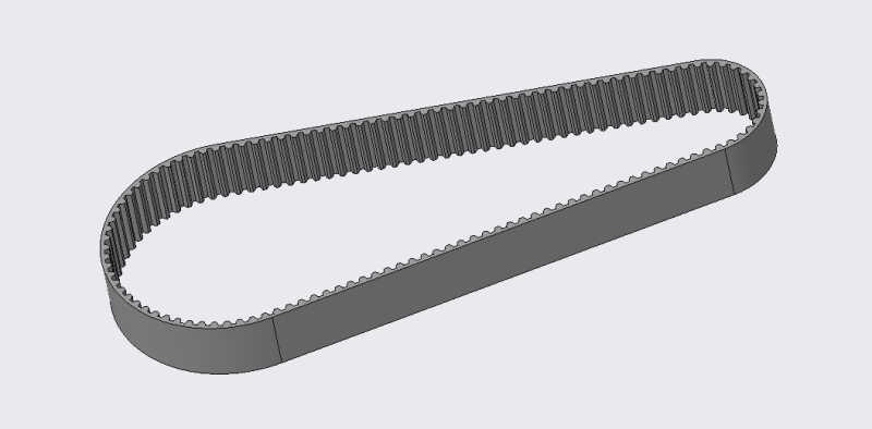
I've created a timing belt path.

Established a pattern consisting of equally groups equally spaced. Each group contains a points and an an axis through that group and normal to the belt inside surface. I adjusted the display on the axis so that the axis points inward.

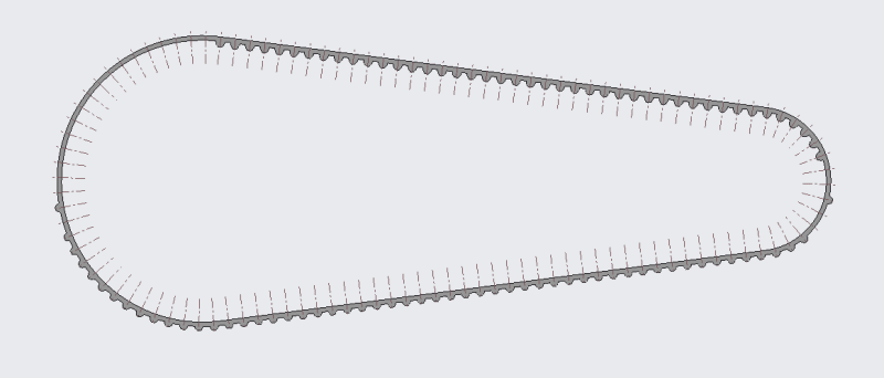
I then created a belt tooth feature referencing ONLY the pattern's first group's point and axis and then reference patterned that tooth feature.

I don't understand why this isn't patterning properly.

Attached are a couple of screenshots and the file.

Thank you for your help!
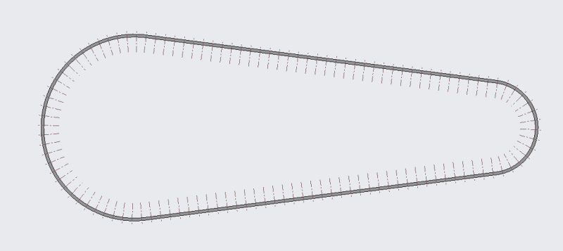
1_cbjppy.png


2_gszvnd.png


Replies continue below

Recommended for you

It's because the requirements are not well defined. Each little bump is on the point and axis and the surface. The problem is that it doesn't have a notion of which way is the surface.

I would be tempted to do this using a spinal bend. Create the full length belt as a straight item and then spinal bend it to match the desired path.

See:

 
Attached is an example timing belt which is automatically generated as a configured Creo file by Stock Drive Components. Their stable and reliable models use a similar methodology to what I have tried. Other than being generated in an older version of Creo, I'm not sure what they're doing differently to successfully create the timing belt tooth pattern.

 
 https://files.engineering.com/getfile.aspx?folder=7bbfc8a1-ead2-4b85-9de9-2268545d3a60&file=SDP_sdpsi_a_6g16m040030.prt
I got the model working.

What it needed as part of the pattern group was a Datum Plane through the point, normal to the axis, and normal to the default front plane. This datum plane gave each of the tooth an absolute direction dictated by the front/back of the Datum plane rather than the ambiguity offered by the axis.

From the working model I showed in the previous post I found an embedded (undefined?) DTM 1 that provided this direction reference. In that model though, I didn't see how DTM 1 was defined.

Thanks!
Screenshot_2024-01-11_090056_ai3pb2.png


I've dealt with a few timing belt 3D models and the ones I inherited were never fully parametric, so well done.

I once had a similar challenge patterning a nub feature on a tire surface, where each nub needed to aimed at a slightly different vector due to the balloon tire contour (anyone remember R/C Team Losi original 'fuzzy' tires?)

Anyway, it took patience but instead of jumping to the pattern, I took my first feature and adjusted all of its parameters until I was satisfied it could regenerate in a variety of possible orientations. Then I could see what was missing or not parametric enough, refine my base feature group, and try again. Then the final pattern worked fine.
 
Status
Not open for further replies.
Back
Top