Eng-Tips is the largest engineering community on the Internet

Intelligent Work Forums for Engineering Professionals

Patterns on Auto rickshaw body 1

Status
Not open for further replies.

Tuco_Salman

Automotive
Dec 10, 2019
4
0
0
IN
Hello All,

I am new to this forum and this is my first question.
I tried searching about this in the forum and please pardon me if it is already asked/posted.

My first question is that what is the significance of the patterns found in auto rickshaw body?
Does the patterns help in giving rigidity to the structure? ( Look at the below images)
What is the purpose of these patterns?

three-wheeler-auto-body-parts-500x500_jqqmrv.jpg


product-500x500_gwmtcu.jpg


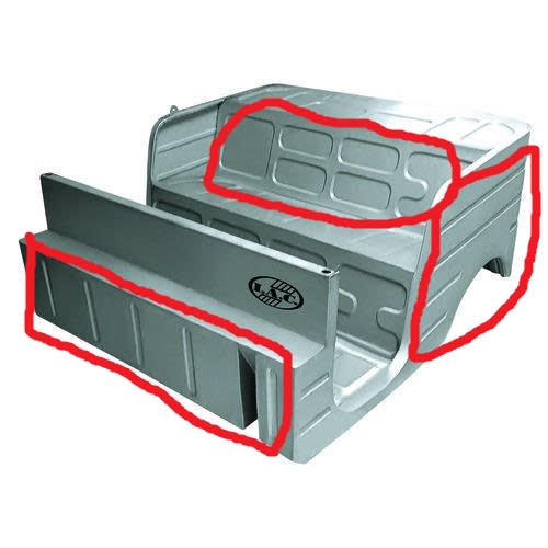
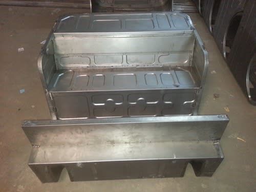
I am trying to build replica of this body design in solidworks using solidworks sheet metal.
My second question is that how to build these patterns in solidworks sheet metal?


Thanks

Tuco
 
Replies continue below

Recommended for you

Probably look into using the form tool in SWX. It looks like you could use a few big tools or repetitions of 8 or 10 different shapes.
 
Brian said:
Carefully placed ribs and indentations and three-dimensional curves add stiffness to the sheet metal.

Greg said:
To add to Brian's answer, they prevent or at least reduce 'oil canning' of the flat panels, which would be very annoying on rough roads and potholes.

What is the minimum thickness of the sheet metal to have the indentations on them?
Does it depend on thickness?
What is the sheet metal thickness used for manufacturing these types of auto rickshaw?

Thanks

Tuco
 
Tuco Salman said:
1) What is the minimum thickness of the sheet metal to have the indentations on them?
2) Does it depend on thickness?
3) What is the sheet metal thickness used for manufacturing these types of auto rickshaw?

1) Minimum is foil to maximum as thick as you can form. Maybe 3mm?
2) Forming force is in tons and depends on sheet thickness and the size of the tool. Since there's few repeated shapes, I'd guess one or two hits on one or two tools for each panel.
3) As a guess, in the automotive range of 20-24 gage or .9-.6 mm. This is easy to change without messing up the other features in solidworks.

As design guidance, I'd find an accessible book on sheet metal structures. Omer Blodgett's books on weldment design go into shape stability and buckling for weldments, I don't think the nomographs cover material as thin as you're working with.

 
I would think minimum thicknesses and the exact shape of the indents would be trade secrets - that in order to find this out, you would need to analyze lots of vehicles, then do lots of modeling, and other kinds testing to determine what works and what doesn't. Not for the faint of heart.
 
Just a side thought:

Those indents not only stiffen the panel, but carefully selected, could reduce the amount of noise generated. Large flat panels vibrate in sympathy with low frequencies and small panels vibrate at high frequencies. By varying the size and location of the panels, the noise generated could be spread-out over a large range of frequencies, thereby reducing the apparent noise level.
 
CapriRacer said:
Just a side thought:

Those indents not only stiffen the panel, but carefully selected, could reduce the amount of noise generated. Large flat panels vibrate in sympathy with low frequencies and small panels vibrate at high frequencies. By varying the size and location of the panels, the noise generated could be spread-out over a large range of frequencies, thereby reducing the apparent noise level.

How to determine the size and location of the indents to be placed?
Is there any method to find out? Is there any source to learn more about this topic?
 
You can use FEA, or you can try hitting various panels and seeing what the maximum flat size is that you can tolerate. Or you can do the tried and trusted technique of copying an existing design. The only slightly interesting thing in your example is the assymetry in seat back.

Cheers

Greg Locock


New here? Try reading these, they might help FAQ731-376
 
By the way, that looks like a neat project. I got my first SWX job because I had a project (an adjustable cable measuring/cutting jig) to point to and say hey look, I can do this. Another interesting problem in the project is how are all of the pieces fit together? The spot welds are the clues for some. Consider that there's a flange from a mating part behind each spot weld.
 
Do you think it sees periodic torsion since the support is always shifting from one pole to the other on a rickshaw as the person carrying it walks?

Nevermind, I see, it's an AUTO rickshaw, I wondered why it looked like it didn't balance over the axel.
 
These are often designed for multiple purposes. Yes they stiffen as the primary use. In the old days people would build a sub-unit form flat panels and measure its stiffness and see where they got distortion. Think of the ribs as being similar to added stiffeners without the added weight, pieces, or work. Today of course you would do this mostly through software.
The reduction of HNV is a side benefit.
With some steels it is also beneficial to cold form them as you increase the strength. So not only does the shape handle the load better but the steel itself may be stronger in areas where it is formed.
These are sometimes also used to create clearance needed for things to fit.
And to some extent the patterns become a trademark (and some are protected as such). It isn't uncommon to see the shape of a companies logo incorporated into these patterns.

= = = = = = = = = = = = = = = = = = = =
P.E. Metallurgy
 
Status
Not open for further replies.
Back
Top