Eng-Tips is the largest engineering community on the Internet

Intelligent Work Forums for Engineering Professionals

PBR panel calculations

Status
Not open for further replies.

kenshrox

Structural
Mar 29, 2023
5
0
0
ES
Hi all,

I am kind of new in the US standards, and I would like to get familiar with the sheeting for roof and walls, specially for warehouse cases.

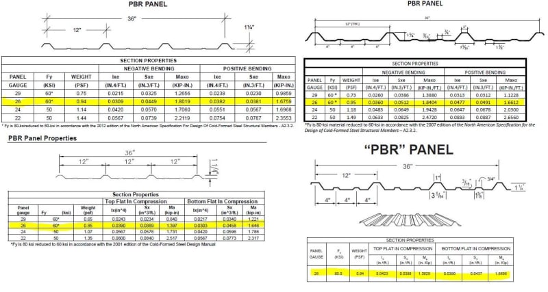
Checking different manufacturers for PBR panel, i have noticed that having each of them the same geometry for the PBR panel, the section properties the net area and the net inertias are not the same, and sometimes not even close.

There are 2 questions that I would be interested in learn:

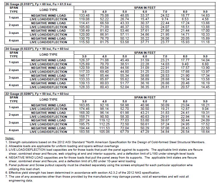
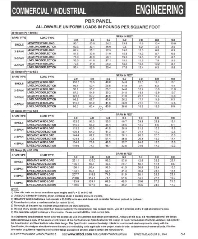
- The tables that the manufacturers provide is to enter with the "real" load, not the factored one, right? (I mean, for instance, for a wall would be the load of the wind using the ASCE 7, and for the roof, the add of the wind load + snow load + roof live load, but not combining with LRFD or ASD) Am i right?

- The second question, and more important to me. If I wanted to do these calculations analitically, I understand that I should be using the AISI S100, but I cannot find/understand well which are the parts of the code that I should apply. Do you know any place with the calculations explained for a case?

Thank you in advance!
 
Replies continue below

Recommended for you

Can't speak specifically for PBR panels, but typically when product suppliers provide a load table, the loads are ASD.

And just to be clear, the "real" load IS the "factored" load. It is the load from your governing load combination.....whether is dead + wind or wind + 10 elephants dancing on the roof.

Why would you want to do the calculations analytically? The product supplier is only going to stand behind their published capacity, not the capacity that you calculate.
 
Thank you for your answer @Motorcity.

So the loads from the tables are usually ASD... nice to know it. From the description on the tables I was expecting that would be the "real" load because it does not say anything about that.

About wanting to do the calculations analytically, I would like to know how far are each supplier from the "real behavior" of the panel, because I can notice that for the same profile section with the same steel grade and also the same thicknesses they have quite different values.

See the images that I attach below, and let me know your thoughts.

Thank you in advance!

PD: Taking advantage of this post, I don't know if you know which is the standars who goberns the calculations of the selfdrilling screws for these panels.

LOADS_PBR_ergdhh.jpg


PBR_SUMMARY_xtylrw.jpg
 
It seems odd that the 26 gauge panels for a single span are rated higher than 24 gauge. That needs to be affirmed by the supplier of the panels.
Fy and Fu are claimed to be 60 and 61.5 ksi respectively for the 26 gauge material. Seems high.
Modulus of elasticity, 'E' was not given, but it usually does not vary much, regardless of Fy.

Are such flimsy panels really used up to spans of 9'-0"?
 
I'm a metal building guy.

I agree that the charts look off because they show the 26 Ga. panels as stronger than the 24 Ga. panels for simple span.

When people choose to do a through fastened roof like PBR (I have no idea why anyone would want a million holes in their roof) 24 Ga. is standard. 26 Ga. used to be more common but it doesn't work well for more recent codes. In any case on a PEMB, the max purlin spacing on a roof would be 5 ft but are typically less than that.

26 Ga. panels are more common for walls where the C&C loads are smaller.

29 Ga. panels are only used as liner panels. That's where you have a thicker panel on the outside of your girts but want metal sheeting on the inside of your building in lieu of leaving it open or doing drywall or whatever.
 
Answering @BAretired/SandwichEngine:
Take a look again and notice that gauge 26 is fy 60 ksi, and gauge 24 is 50 ksi, so maybe for the differente of fy can be the difference of behavior. Maybe depending if it is a single span where you just have the top part of the panel in compression or multispan where the maximum bending moment you have it at support and compressions can be in bottom part of the panel can provoke those difference, that's why I want to calculate it.

And about the distance of 9', for PEMB , I think you put this maximum distance in walls, because in the walls, as you have less load than roof, you can achieve this separation for girts. In the roofs as SandwichEngine says, maximum is usually 5' because these panels of 1 - 1/4" depth can not hold the load needed at more length than that.

But coming back to the topic:
- Does anyone knows how to calculate a PBR table? With which exactly standard? Any example?
- Does anyone knows the standard/code for calculating the selfdrilling screws?
 
I was aware of the difference in Fy and Fu (60 & 61.5 ksi vs 50 & 60 ksi) for 26 ga. vs. 24 and 22 ga. panels respectively, but a ratio of Fu/Fy of 1.025 seems unusually low for steel, so I suggest you ask the supplier to confirm those values. I do not believe them.

For strength calculations of the panels, see Note 1 below the load tables.

There are many types of self drilling screws. Values of shear, pullover and pullout are determined by test. The Simpson Strong-Tie chart below provides values for one particular screw, but 22 ga. is the maximum panel thickness considered. For lighter gauge material, you may wish to look at the standard referenced in Note 2. I am not familiar with it.

Capture_x3vhte.jpg
 
I sent some questions to the supplier but they are not answering at all.

From my guess point of view, I noticed that the 26/60, the material is not 60 ksi, in reality is 80 ksi, but they limit to 60 ksi. So limitating the Fu to 61,5 ksi it can be a way to reduces also the capacity of the material in pose of the safety. That would explain the difference between the 24/50 and 26/60, because the tables are limited not only by strength but also for deflections. So maybe when they are by strength the code can allow for the parts of the panel which works in tension to achieve the Fu and for the compression ones to achieve just Fy.

That's why I wanted to see some example of calculations of these tables and understand how is the code applied with some examples.
 
I came across some other tables for PBR panels (see below). The values for 26 gauge panels seem to be in close agreement with your values, but I have not done a rigorous comparison of the two sets of tables, nor have I attempted to check the calculations using normal principles. The tables below list Fy as 60 ksi for 29 and 26 gauge panels. I would not assume Fy = 80 ksi for any panel without a guarantee that it is so.

So far as example calculations, I would rely on normal structural engineering theory, but cold formed shapes are a bit tricky to design. Sometimes panel width is reduced to "effective width" to account for local buckling, but I am not current on the design of such elements.

Capture_u5apyv.jpg
 
Thank you @BAretired,

In other codes, I am a bit used to calculate that kind of cold formed profiles (in others codes for these thin plates are called class 4, because of the net area and gross area are differents, as you said before, due to local buckling).

That's why I wanted to see some US examples to get used to that code.

Thank you for your time :)
 
Status
Not open for further replies.
Back
Top