Hi,
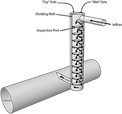
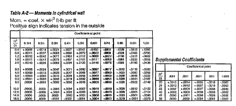
I am working on a design for a Vortex Drop Structure and I am intending to use the "PCA circular Tank" document as a design reference. However, the parameters for my drop shaft are wayyyy beyond the "H^2/(D*t)" values provided in the appendix and the supplemental of the PCA circular tank document. My shaft is about 40ft dia. and extends nearly 200ft into the ground. I've been told that thicknesses of 2-3 ft are typical for these structures.
Since I am unable to use the PCA design tables, I decided to model the tank using Staad with fixed-pinned boundary conditions at the base and top of the shaft in order to determine the hoop stresses and moment demand.
My results are showing some pretty high moments at the base where I need bundled (2)-#11 bars at about 8" spacing. I thought this seemed reasonable given the 200ft depth, however, I have seen designs for similar shaft dimensions, but slightly shorter depths showing only single #8 bars at 12" spacing.
Does anyone have any experience designing these types of structures? Is the fixed pinned condition too conservative for design? or should I incorporate some soil springs?
Is there a reference that is more up to date or more appropriate to use than the "1993 PCA Circular Tank" article? I mean it is 2023 now.
Any advice would be greatly apprecated.
Thanks