Eng-Tips is the largest engineering community on the Internet

Intelligent Work Forums for Engineering Professionals

Permissable touch voltage - derivaton of curves in EN 50522 1

Status
Not open for further replies.

Electrical1948

Electrical
Apr 18, 2015
16
0
0
NL
Hi

Referring to thread238-305712.

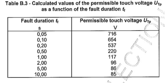
Im trying to derive the permissable touch voltage curves in standard EN50522 without any success.

Can someone please share how to derive these curves? An ExCeL worksheet will be appreciated:)

Many Thanks
 
Replies continue below

Recommended for you

EN_50522_B3_mrfdxn.jpg

Using the list in Table B.3 where some points appear, you can find the other points by interpolation. More precisely, you can copy the curve and measure the paper in mm and calculate proportionally.
 
The permissible touch voltage per IEC can be estimated by the product of the permissible body current for an electric shock duration t, times the sum of the body resistance for the path specified by the touch voltage plus the feet to soil resistance for touch voltage.
For additional details, see the enclosed excerpt and the references.
 
 https://files.engineering.com/getfile.aspx?folder=3ec73a52-0246-48f3-b0d7-ccbc8526eeae&file=GROUNDING_-_Comparison_IEC_&_IEEE_Std_80.pdf
Thanks cuky2000, but this does not explain how to derive the values given in table B.3 in EN 50522.

However the standard gives some hint on how to derive the curves given the formula in Annex A and values for body impedance and body current given in annex B.

The curve in figure 4 in the standard are based on weighed averages for permissable touch voltages as discussed in thread238-305712.

User Radug came Close to calculate the values, so his input will be valuable.
 
To obtain a value of Table B.3, you must solve a non-linear circuit with R= r(i) (or R= r(v)),
for each possible circuits as the Standard shows, with different corrections factors HF and BF, and
calculate a weigthed average.

I have a program to do this job, without additional resistance and with the values of additional
resistance from Standard.

The program generates a lot of values, for you request of t=0.05 s, the Table B.3 has the value 716 V,
the program calculates 712.84 V.

TABLE C.3 AND FIGURE 9.1


TIME OF FAULT : 0.05
HF : 1.
BF : 0.75
WEIGTH : 1.
TOTAL ADDITIONAL RESISTANCE : 0.
BODY RESISTANCE : 820.939836 at 554.13439 V
CORRECTED BODY RESISTANCE : 615.704877
TOTAL TOUCH RESISTANCE : 615.704877
PERMISIBLE BODY CURRENT : 900.
PERMISIBLE TOUCH CURRENT : 900.
BODY VOLTAGE : 554.13439
PROSPECTIVE TOUCH VOLTAGE : 554.13439


TIME OF FAULT : 0.05
HF : 0.8
BF : 0.75
WEIGTH : 1.
TOTAL ADDITIONAL RESISTANCE : 0.
BODY RESISTANCE : 780.306292 at 658.383434 V
CORRECTED BODY RESISTANCE : 585.229719
TOTAL TOUCH RESISTANCE : 585.229719
PERMISIBLE BODY CURRENT : 900.
PERMISIBLE TOUCH CURRENT : 1125.
BODY VOLTAGE : 658.383434
PROSPECTIVE TOUCH VOLTAGE : 658.383434


TIME OF FAULT : 0.05
HF : 1.
BF : 0.5
WEIGTH : 1.
TOTAL ADDITIONAL RESISTANCE : 0.
BODY RESISTANCE : 929.401269 at 418.230571 V
CORRECTED BODY RESISTANCE : 464.700634
TOTAL TOUCH RESISTANCE : 464.700634
PERMISIBLE BODY CURRENT : 900.
PERMISIBLE TOUCH CURRENT : 900.
BODY VOLTAGE : 418.230571
PROSPECTIVE TOUCH VOLTAGE : 418.230571


TIME OF FAULT : 0.05
HF : 0.4
BF : 1.
WEIGTH : 0.7
TOTAL ADDITIONAL RESISTANCE : 0.
BODY RESISTANCE : 775. at 1743.75 V
CORRECTED BODY RESISTANCE : 775.
TOTAL TOUCH RESISTANCE : 775.
PERMISIBLE BODY CURRENT : 900.
PERMISIBLE TOUCH CURRENT : 2250.
BODY VOLTAGE : 1743.75
PROSPECTIVE TOUCH VOLTAGE : 1743.75


TIME OF FAULT : 0.05
HF : 0.04
BF : 1.
WEIGTH : 0.
TOTAL ADDITIONAL RESISTANCE : 0.
BODY RESISTANCE : 775. at 17437.5 V
CORRECTED BODY RESISTANCE : 775.
TOTAL TOUCH RESISTANCE : 775.
PERMISIBLE BODY CURRENT : 900.
PERMISIBLE TOUCH CURRENT : 22500.
BODY VOLTAGE : 17437.5
PROSPECTIVE TOUCH VOLTAGE : 17437.5
average 712.843349
==================
---------- values for different times were deleted
==================
RF = 0.0000 OHM
NR. Tf (S) UvtP I Table B.1 Table B.3
----========------------============
1 0.05 712.8433 900.0000 716.0000
2 0.10 610.6242 750.0000 654.0000
3 0.20 508.3179 600.0000 537.0000
4 0.50 219.5357 200.0000 220.0000
5 1.00 116.7734 80.0000 117.0000
6 2.00 95.6989 60.0000 96.0000
7 5.00 85.4868 51.0000 86.0000
8 10.00 84.3328 50.0000 85.0000

Sorry, my English is bad.

Regards,

OPH. 2018-04-27 05:34
 
Thanks Erdep. This is interesting!

How do you calculate the average of 713 V?

Im calculating as follows which may be incorrect:

554 + 658 + 418 + 1744*0,7 / (1+1+1+0,7) = 2851 / 3,7 = 770 V. What am I doing wrong here?
 
Thank you for you post, erdep. However, there are some incomprehensible points.
For instance, what does mean PERMISIBLE TOUCH CURRENT?
What formula did you use in order to calculate VTP?
It is not from Annex A Utp=Ib(tf)*ZT(Ut)*BF/HF.
For instance for left hand to feet :
Utp=0.9*615.7*0.75/1=415.6 and not 554.13
 
For Electrical1948:

(554+658+418+1744*0.7)/4= 713

For 7anoter4:

Thank you for you post, erdep. However, there are some incomprehensible points.
For instance, what does mean PERMISIBLE TOUCH CURRENT?
What formula did you use in order to calculate VTP?
It is not from Annex A Utp=Ib(tf)*ZT(Ut)*BF/HF.
For instance for left hand to feet :


1) Utp=0.9*615.7*0.75/1=415.6 and not 554.13

The factor 0.75 is taken into account when the non-linear circuit is solved

Utp=0.9*615.7/1= 554.13


2) For instance, what does mean PERMISIBLE TOUCH CURRENT?


Permisible Touch Current is the current in the circuit with the same
effect in the heart as Hand to Hand (HF=1.0).

For example, for feet to feet circuit with HF =0.04, this circuit
allows 900/0.04 = 22500 mA, with 900 mA in the heart.

In this case, it is step voltage, we may accept it is a special case
of touch voltage.

This enormous allowed current is the reason to not calculate step
voltage/current. It is not taken into account in the average.

I have a program to verify ground grids that uses this Standard (and
IEEE 80). IEEE 80 requires step voltages calculation.

The programs are free, but I am not sure if I can add a link here.

OPH.


Thanks Erdep

How did you calculate the different Z(Ut) by the way? In EN50522 only 775 V for the highest touch voltage is stated, while you have calculated different values depending on the different circuit configurations.

I think you can attach the programs to this thread.
 
In Table B2 R(V)= 775 Ohm for 700 V and 1000 V, I assumed R= 775 Ohm for V>1000 V.

Tha values are rounded to 25 Ohm, it make difficult to obtain more accurate result
for different voltages not in the table. I used interpolation.

By the way, it is convenient to use interpolation in log(x) and log(y) tables for all variables (R(v), I(t), etc.)

This may be not true for high values of V, but is that I have.
Such values are for very short times, habitually the protection times are bigger, say 0.5 to 2.0 s.

Table B.3 and Fig. 4 of EN50522 are for Raditional=0. Figure B.2 are for different Raditional.


The programs can be downloaded from:


Both the titles and the manual are in my English...

All was done as hobby, surely a commercial program does all better, but not as cheap.
 
Hi

Thanks for Your post. It clears up a lot!

Im trying to create the table below from your previous post in the program. I assume I have to change some data in the SAMPLE.dat file then run erdep 2? Correct?


1 0.05 712.8433 900.0000 716.0000
2 0.10 610.6242 750.0000 654.0000
3 0.20 508.3179 600.0000 537.0000
4 0.50 219.5357 200.0000 220.0000
5 1.00 116.7734 80.0000 117.0000
6 2.00 95.6989 60.0000 96.0000
7 5.00 85.4868 51.0000 86.0000
8 10.00 84.3328 50.0000 85.0000
 
Erdep1 is for uniform soil, erdep2 is for two layers soil.

To obtain any value of the table you must run the program four times, with

HF= 1.0, 0.8, 1.0, 0.4
BF= 0.75, 0.75, 0.5, 1.0
Weigth= 1.0, 1.0, 1.0, 0.7

and calculate the average.

The table shown is for Raditional=0.0

The Rad can be added in a line with $F.

This value is for Rho=0.0. The programs erdep* dislike Rho=0.0, use a small value, say 0.01.

All the cases of Fig. B2 of EN50522 (Rad= 0.0, 750.0,1750.0,2500.0 and 4000.0D0 Ohm)
are calculated by the program en505222010.exe


For the programs erdep* you can use the values as indicated in Fig. B2.
Recall they calculate one circuit at time.
 
Status
Not open for further replies.
Back
Top