Continue to Site

Eng-Tips is the largest engineering community on the Internet

Intelligent Work Forums for Engineering Professionals

  • Congratulations SSS148 on being selected by the Eng-Tips community for having the most helpful posts in the forums last week. Way to Go!

PIN or FIX support? 4

Status
Not open for further replies.

Jandra11

Structural
Jun 18, 2017
109
pin_support_1_zsxprv.jpg
pin_support_2_ftl8iz.jpg

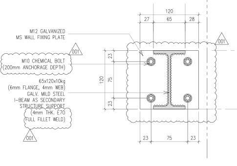
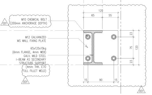
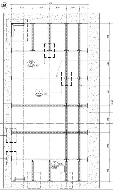
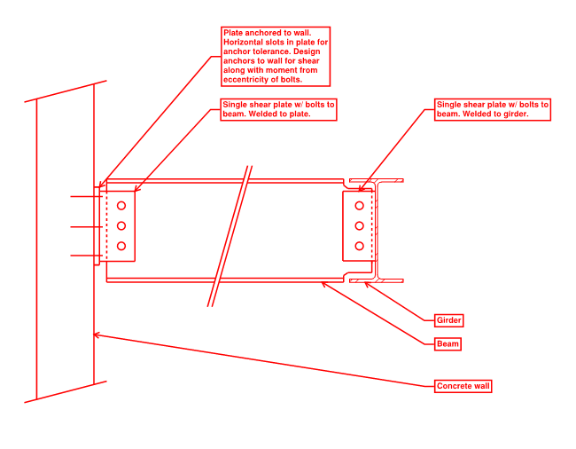
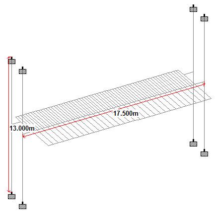
These are the lay out of the supports. Its an I beam that support a platform and it was connected to a concrete structure. can i assume this support as a PIN support at major axis and FIX support at minor axis so i can reduce the stress on the bolt and at the same time to reduce the LE consideration for LTB check? Can i assume that its a PIN support as long as the bolt is inside the section's Flange. Or can i consider it a FIX support as long as it can resist the moment reaction even though the lay out of the bolt is inside the section's flange? All opinions are very much welcome. thank you in advanced
 
Replies continue below

Recommended for you

We get a lot of this type queries. Rarely is a connection either completely fixed or pinned.
 
Can be fixed...an be hinged...can be something in between
depends on the rotation ....


best regards
Klaus
 
yes, the world is full of shades of grey, but sometimes we have to pick black or white.

the most conservative approach would be "overlapping assumptions" ... pick pinned when analyzing the beams (as this should cause the highest stresses in the beam), pick fixed when analyzing the ends (the welds, fasteners, and local structure).

another day in paradise, or is paradise one day closer ?
 
You'll absolutely generate some meaningful strong axis moment at the connection. So I would consider that moment in the design of your bolts.

For lateral torsional buckling:

- I would certainly consider the joint torsionally restrained.
- I would not consider the joint torsionally fixed as that requires a degree of weak axis (flange strong axis) joint stiffness that is difficult to guarantee.

Overlapping, as rb1957 said.

I like to debate structural engineering theory -- a lot. If I challenge you on something, know that I'm doing so because I respect your opinion enough to either change it or adopt it.
 
It's definitely going to behave fixed (or close to it) about the weak axis.

Whenever I am in doubt about something like this I'll run it both ways and be sure the detail can handle the reactions for either one.
 
thank you guys for the response.the members are all fabricated. and as i checked the design i noticed that the end plate connection cant carry the the moment reaction. thats why i decided to make it a pin support, and as far as i know i can consider its a pin support as long as the bolt are position between the flange of the I beam. Is there more efficient way to make sure the the support would carry a minimal moment reaction?
 
OP said:
as far as i know i can consider its a pin support as long as the bolt are position between the flange of the I beam.

I'm afraid that this is an unfortunate myth. If anything, this arrangement exacerbates tension in the bolts and the forces that tax the connection plate by reducing the lever arm over which the inevitable moment acts.

OP said:
Is there more efficient way to make sure the the support would carry a minimal moment reaction?

One alternative:

- bolt a loose plate to the concrete.
- weld a standard AISC double angle connection to the loose plate.
- SSL or LSL holes for errection tolerance.

This may not jive with your corrosion protection strategy, however, as field welding would require touch up work on the galvanizing.

Another alternative:

- support the beam on a seat angle bolted to the concrete.
- install a bolted web angle with LSL holes to prevent roll over.

I like to debate structural engineering theory -- a lot. If I challenge you on something, know that I'm doing so because I respect your opinion enough to either change it or adopt it.
 
Are both ends of the 65 X 120 beam supported by the same detail ?
 
What is the lateral system of your platform? If you don't have a moment frame or braced frame, the baseplates will (and can) resist moment.
 
@tmoose yes both ends have the same connection detail
@motorcity this is the framing plan
plan_d8fyuv.jpg
 
You may have a fit up issue in some spots as it is. With those connections at both ends, you don't really have a way to adapt to tolerances, or even get the members in there, unless your plan is to leave gaps at the ends and fill them with grout later etc.

I like to debate structural engineering theory -- a lot. If I challenge you on something, know that I'm doing so because I respect your opinion enough to either change it or adopt it.
 
Use double angle connection, either bolted or field welded so you can install the beam. This will also solve the issue of fixed/pin.
 
Double angles are favored in North America. In most of the rest of the world, the connection would best be made as a single shear plate. End plates on both end of the beam will make installation impossible. Bolt fabricated tee sections to the wall, and bolt the beams to them.
 
Here's what I would do:
beam_conn_znxzts.png


A loose plate anchored to the wall is really easy to fabricate. Horizontal slots in the plate allow some tolerance for anchor placement. The contractor can choose to weld the shear tab in the field or in the shop.
The same connection on the other end is really simple.

The anchors to the concrete are designed for the shear from the beam along with the moment created from the bolts being eccentric from the concrete by a few inches.
 
The west coast would have had a embed plate with single shear plate with slotted holes and a welded plate washer, welded after dead load has been applied. Trying to keep the connection close to what is currently proposed, I find that double angle has more flexibility than WTx and no welding of shear plates.
 
can i use that pin connection detail on column? or is there other advisable approach ? Im getting 30mm thickneness plate when i consider it as a support using a hilti software. Btw im designing canopy(see picture for ref
plate_qkfclu.jpg
)
 
Status
Not open for further replies.

Part and Inventory Search

Sponsor