Continue to Site

Eng-Tips is the largest engineering community on the Internet

Intelligent Work Forums for Engineering Professionals

  • Congratulations KootK on being selected by the Eng-Tips community for having the most helpful posts in the forums last week. Way to Go!

Pinned Base Assumption - Model vs Anchors

Status
Not open for further replies.

JR55

Structural
Nov 9, 2022
21
I know the fixity of the column base plate has been discussed extensively, and that the pinned or fixed assumption in the model is not fully representative of what is practically occurring as there is no 100% pinned or 100% fixed connection.

However, I am wondering if there is any direct guidance from ASIC or otherwise that states a column base plate with 4 bolts inside the flange of a W section can be modelled as a true pin? Seems to me typical engineering judgement is to model this as pinned and design the anchors accordingly without necessarily considering the rotational stiffness of the base plate, foundation, and anchor bolt elongation.

Assuming generally light loading and a structure designed to carry the moments needed to model a pinned base, does anybody have any guidance that explicitly allows the base plate to be designed as a pinned? Applying moments to the anchors of moment resisting frames doesn't seem to me like standard practice, but I may be wrong.

Another way to ask my question - Is standard engineering practice to model as a pinned base and subsequently design the anchors as a true pin as well without considering rotational stiffness (assuming there are no instabilities in the frame)? If so, is this supported by anything other than engineering judgement?
 
Replies continue below

Recommended for you

I consider a base to be pinned unless I specifically design it to be fixed. Even base plates with anchor bolts OUTSIDE the flanges I consider pinned.

DaveAtkins
 
JR55 said:
Is standard engineering practice to model as a pinned base and subsequently design the anchors as a true pin as well without considering rotational stiffness (assuming there are no instabilities in the frame)?

Yes, that is the standard practice. If the design is carried out correctly, the frame will have sufficient stiffness elsewhere and this particular column base will see little of the load at ultimate levels. You'll also have a thinner base plate, which will reduce the stiffness of the connection.

It's mostly judgement, but that judgement needs to be based on an understanding of the how varied stiffness throughout the frame influence the way it performs and how the loads are resisted.
 
That's what I figured. And because it's mostly judgement, I'm assuming there's no direct references allowing this? I am getting some push back where someone wants to apply moment to all W section connections independent of base plate thickness, which seems needlessly overcomplicated at best.
 
The best you could do would be to try to estimate the actual stiffness of the connection at ultimate load - difficult without software like IdeaStatica. If you have that, you can model it, find the stiffness, and then apply the actual stiffness of the connection in your model to see what kind of loading it attracts.

Who is telling you to do this?
 
If the foundation beneath the baseplate can rotate even by a small amount, the frame model wants to have a pin at the base. You can do your damndest to get a fixed baseplate but if the foundation is rotating then its still a pin. Celt has posted an article about what size pad footings are needed to get a fixity, depends on the column size, footing size, and soil stiffness. If I have time I will find the post later and reference it here. I know this isnt exactly what you have asked, but its something I consider when determining if I can get fixity or pin at the base of a column.
 
Good point, drift. When added to the lack of stiffness in the connection anyway, foundation rotation neuters load 'attraction' even more.
 
right so thats why the typical assumption is pinned base. Its conservative for frame stability. If I truly need fixed then I start making sure we have a stiff foundation element capable of resisting the moments, then check the anchors and baseplate assembly for the applied moment. Getting the moment out of the baseplate is actually pretty easy, the anchors and the foundation are the part where things get crazy.
 
What happens when we get into performance based design?
I know. I'm a trouble maker.
:)
 
driftLimiter said:
Getting the moment out of the baseplate is actually pretty easy
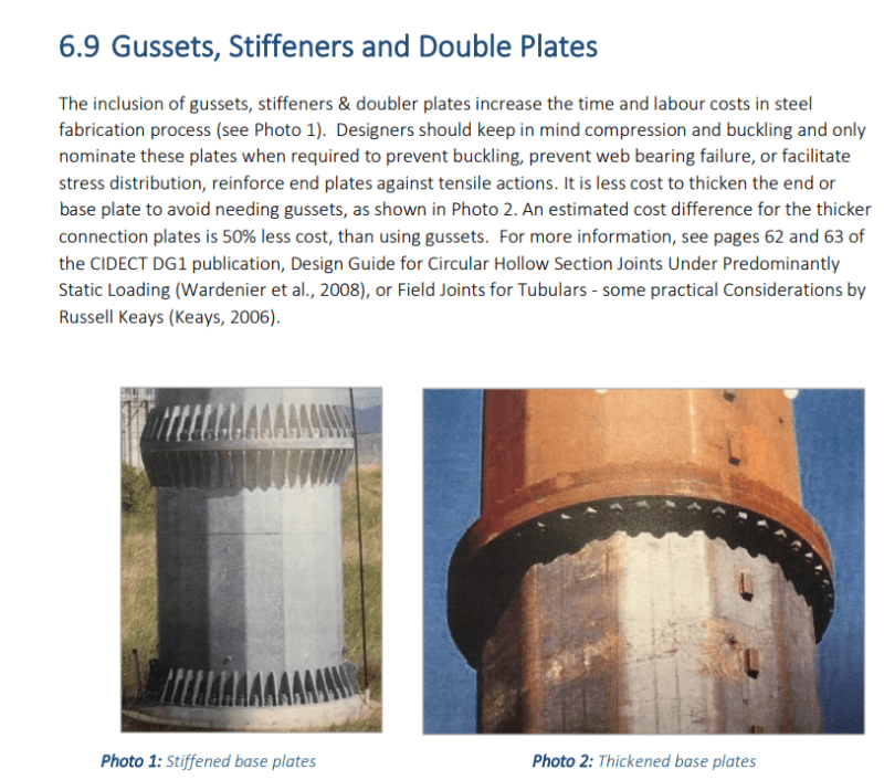
How often to you need to gusset those baseplates? I realize this is a function of demand, but I'm curious where you draw the line between a thick baseplate and the need for gussets.
I was always taught to gusset the base plate to get the connection as rigid as possible. I'm asking because I find it odd how little information there is to analyze these sorts of things. I'm still using the approach presented in Blodgett's Design of Welded Structures. Maybe I'm just not looking in the right place. I also don't use software like Pham mentioned.
 
Good comments by diftLimiter. Most simple foundations (eg isolated pad footings) have little rotational rigidity and so will move if pushed. As commented by phamENG you'll almost certainly have sufficient stiffness elsewhere that the rigidity or partial rigidity of the base plate doesn't matter. In some cases I've modelled the base as 'pinned' yet geometric constraints has meant I've had to have 4+ large bolts outside the flange and a thick baseplate. This is a rigid connection but assuming it as pinned in normally conservative. (Though a cursory check that the rigid won't have negative consequences is advised.)

Other times rigidity that attracts load can be extremely bad. I've posted images of a ball and socket column base here before. Such designs are necessary for example when the structure is designed to have higher deflections than normal.

StrEng007 said:
How often to you need to gusset those baseplates?
Never. (I've used up to 60mm thick plates to avoid gussets. 170kg, 375 pounds per base plate)

Gusseted base plates should be avoided if you can. They are expensive. There are numerous resources that advise this. And it is certainly the case if I talk to my local fabricators.
temp_wcgsvs.png


I'm sure there are many cases where they really are needed once the size of the welds get completely unmanageable. But generally thick places with multipass fillets are easy and cheap solutions.
 
You could download IDEAStatica for a trial. With that you can run an analysis to find the stiffness of the connection. I think you will be surprised.
 
The Eurocode has provisions for calculating column base spring constants for global stability. I use these provisions when I want to model the base stiffness in a nominally pinned-base moment frame and I'm having trouble staying under the drift limit.

There are times where I've modeled a pin base for the structural analysis, then ran the same model with fixed bases to design the base plates and anchors for the base moments. That's not typical though, just when I felt it was warranted for conservatism in the anchorage design.

I don't think there is anything codified about when to model stiffness or assume pin/fixed column bases. It's just judgement and traditional practice.
 
ASIC has a design guide coming out to address base stiffnesses and modeling techniques. I have not seen it actually published yet, but I did attend a seminar. It looks promising.
 
It does seem like research has pushed the development of more refined column base modeling techniques, which will probably end up becoming more ingrained in practice. But I think it will be limited to Performance Based Design purposes. That's basically what I use it for when I'm trying to get more realistic drift results.
 
Status
Not open for further replies.

Part and Inventory Search

Sponsor