BK76:
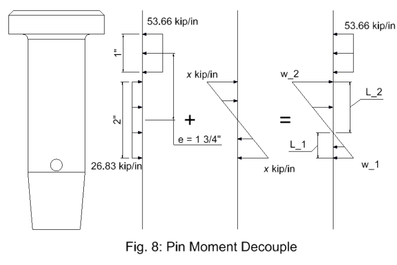
Think about that connection/joint in a little finer detail, and redraw your free body diagrams. There is some dia. and size tolerance btwn. the pin and the holes which actually allows the pin to cock off its drawn axis in the holes, and the plates will move a little when the joint is loaded. This causes concentrated bearing and yielding in bearing at the edges of the holes in the plates. So, your pin loadings are not really straight line or triangular loading diagrams. They are more likely trapezoidal or curvilinear in their shape of the load or stress intensity as the bearing yielding or some minor pin bending takes place. If you have any pin bending it will more likely occur over some distance on either side of the faying surface; and the more so if the faying surfaces can actually separate, thus increasing the lever arm length btwn. the reaction center points. Under normal conditions some yielding in bearing, in the hole, is not a likely failure mechanism and we don’t worry much about it. You can see this yielding and peening of the holes on joints that have been worked for a while. It just allows the pin to seat so there is a sufficient bearing area btwn. the pin and the holes to take the load. Your left most diagram should at least be two trapezoidal shapes, with the max. stress intensities near the faying surface. If the fit is loose enough you could get diagrams in both plates which look more like your middle diagram. Also, take a look at Hertz stresses as they are related to pin bearing in a hole. Remember, these movements, rotations, strains are pretty small for this all to happen under normal conditions.

