Eng-Tips is the largest engineering community on the Internet

Intelligent Work Forums for Engineering Professionals

  • Congratulations waross on being selected by the Tek-Tips community for having the most helpful posts in the forums last week. Way to Go!

Pipe Line Sizing - Water vs. Gas vs. Vacuum

Status
Not open for further replies.

mjkey

Mechanical
Aug 8, 2016
8
0
0
AU
Hi guys,

I've come across a problem which I can't seem to find an answer to online.

Is there any difference between the method of sizing pipe with water flow (say chilled/condenser water) or gas flow or vacuum air flow?

The reason I ask this is because of the following attached charts from a handbook I use.

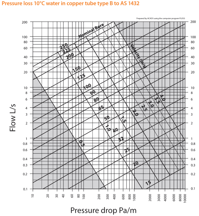
1. Looking at the water chart, the X-axis has a pressure drop per metre, and based on the flow rate I can select a nominal pipe diameter. I've used this extensively in my CHW/CDW designs and understand how to use it.

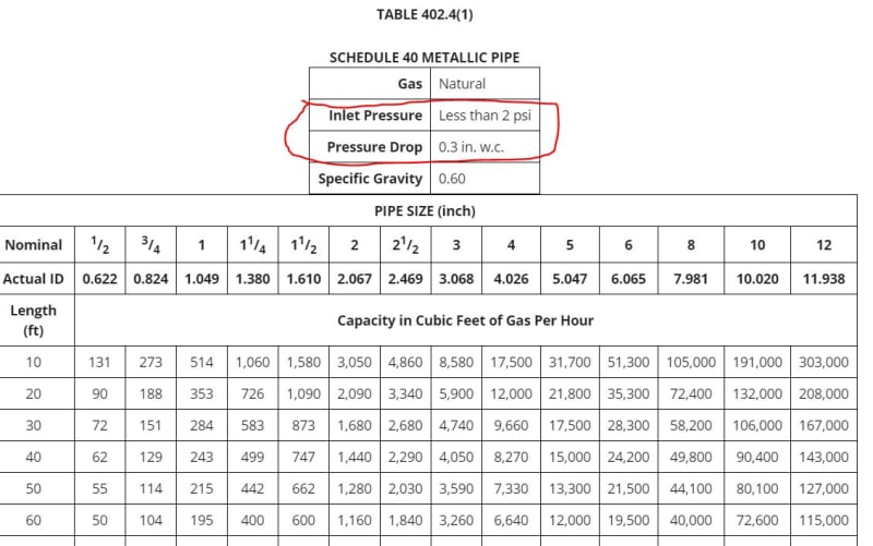
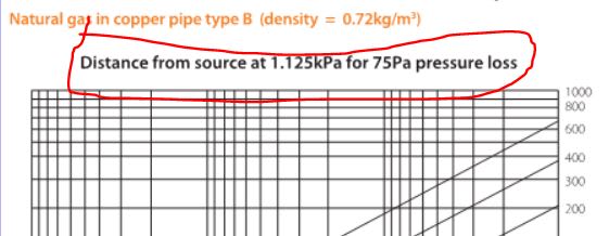
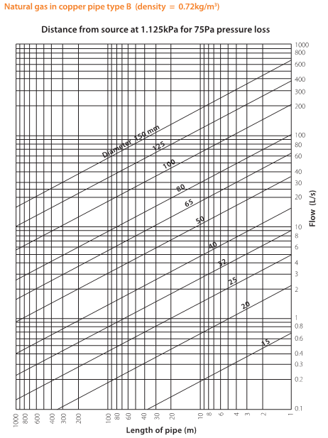
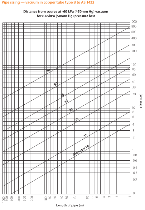
2. Looking at the gas and vacuum pipe sizer charges, can someone please explain for the gas chart what the "Distance from source at 1.125kPa for 75Pa pressure loss" means? My understanding of this is that the 1.125kPa is the available pressure in the system from some sort of pump. But what is the 75Pa pressure loss? There is a similar title for the vaccuum chart.

3. Why is the chart for gas and vaccuum different to the water chart? Is a different method used to size gas/vaccuum pipes? Is this using the "longest run method"?


9FA59909_cfuq3f.png

8435B76_gafjd5.png

3062A8FF_zq16ty.png


Cheers
 
Replies continue below

Recommended for you

They are different fluids, of course the charts will be different.

for water systems, you determine the pressuredrop, and then size a pump to create the pressure. For fuel gas, there is a set pressure (from utility) that can't be changed and you size the piping to have a specific pressure left at the device (based on device manufacturer requirements, often 7" etc.). So you kind of do it the reverse way.
Look up commented version of IFGC for fuel gas pipe sizing guidance.
 
Gas is compressible so flow rate changes as pressure changes. Pressure drop per ft for a gas will change with both source pressure and pressure drop along the length of pipe. Therefore this information is far more complex and not a useful way to present the data.
 
@EnergyProfessional
@Compositepro

Thanks for that explanation guys. Makes sense now with the reminder that gas is compressible (facepalm).

I had a look at the IFGC guide and the tables within, I understand how to use the charts and size the pipe (eg. longest length method).
However I'm still confused as to what the information regarding the "Inlet Pressure" and "Pressure Drop" mean at the top of the tables. I assume this is the equivalent to what it says at the top of the charts that I use "Distance from source at 1.125kPa for 75Pa pressure loss". Could you guys please explain this?

Capture_gpq80k.jpg


Capture1_a1tufb.jpg
 
For fuel gas you have 2 constants you can't change. the pressure from the utility (often 0.5, 2 or 5 psi), and the required pressure at the appliance (often 7 in-wc, or 1/4 psi) or the inlet of pressure regulator of that appliance. You can have the utility change the pressure within reason, but then the entire system needs to be built for that. the above pressures are "typical". you cannot change the appliance requirements.

So the maximum pressure drop with all appliances burning at 100% must not be more than the difference between utility pressure and appliance requirement.

you probably saw there are multiple tables for different pressure drops. You have to sue the appropriate table inc. safety factors. If you have 2 psi utility, and 1/2 psi at appliance, you must use a table with less than 1.5 psi pressure drop. Note that a pressure regulator that gives you 1/4 psi for the appliance may have a minimum pressure requirement of 1 psi. so you piping would have to have less than 1 psi pressuredrop in a 2psi system.

Whenever I have the choice, I change the facility piping to 5 psi. That allows smaller pipes but requires appliance regulators. Some designers (or owners) choose the utility to provide 1/2 psi and use larger pipes, but don't need appliance regulators.
 
I think what this is is to limit the calculation to a gas which essentially is at a fixed density. It also I guess limits the maximum velocity

I'm not sure what 0.3ic wc is versus 2psi, but it looks like virtually no pressure loss at all. But as it says less than 2psi so could be inches of wc and your flows are still ok, because the pressure drop is a bit higher than at 2 psi, but the density is about the same.

75kpA on 1.125 is about 6% loss. that's only 0.15 psi (1.125kPa)

How and why they choose those numbers who knows?


Remember - More details = better answers
Also: If you get a response it's polite to respond to it.
 
Most gas companies limit your pressure drop to 0.3 in w.c. or 0.5" w.c. It is a slightly more significant pressure drop when your starting pressure is 7" w.c. At pressures measured in psig, it is virtually nil.

I would also recommend using some of the charts with a large grain of salt (at least the ones in the newer versions of the code).

There is a chart in the 2015 IFGC with a starting pressure of 5 psig and a pressure drop of 3.5 psig. That is a 70% pressure drop.

Based on Cranes TP, you should only use 20% pressure drop for D'Arcy equations, up to 50% pressure drop if you use the average density at the two pressures and anything beyond 50%, you use empirical formulas.

The equations used to derive the tables in the IFGC make no mention of this.

They used to have tables for starting pressures measured by in w.c. Now they only have the less than 2 psig, which is totally worthless because in building the tables, they use a different equations for P<1.5 psig and P>1.5 psig.

Personally, I don't use the tables. I built a spreadsheet around the two equations and use that.


Pedarrin2: An appliance pressure regulator has a minimum inlet pressure of 1 psi. In a 5 psi system and 3.5 psi pressuredrop, that leaves you at a comfortable 1.5 psi.
Why would you not take advantage of the higher allowable pressure drop? If you limit pressure drop to 0.3" or similar, you end up with huge pipes at significant cost.
Sure, it will work since it will be more than over-engineered, but will be costly.
 
I do agree using a 2 psig inlet with a 0.3 in w.c. pressure drop is overkill. The older versions of the IFGC had tables where the starting pressure was less, i.e. 7 in w.c. For that starting pressure, a 0.3 in w.c. loss is more applicable.

But I do have some questions/comments.

1. Why do you have 5 psig in the building if you only need 1 psig at the equipment regulator? If you can use 2 psig, then a 1 psig drop is still within reason (barely)
2. Why pick an equipment regulator that has a 1 psig minimum? What pressure is needed at the piece of equipment? Is it 14", 7"? If the equipment doesn't need a lot of pressure, choose a different equipment regulator and run lower pressure in the building.
3. I am not saying you cannot start with 5 psig and end up with 1.5 psig. What I am saying is the tool being used (IFGC Table) is based on equations that do not take gas density into account. According to Crane TP, which uses D'arcy for compressible flow, you don't have to account for density changes if the dP <0.2P1. If 0.2P1<dP<0.5dP, you use the average of the two densities. If dP>0.5P1, you have to use empirical formulas. The equations in the code are empirical - but do they also work for when dP<0.5P1? I do not know. Again, I go back to Crane TP. It actually does a comparison of different natural gas equations to show how each give different results. There are constraints on all of them which indicate when they should and should not be used. Some of the tables in the IFGC even contradict the boundary conditions of their own equations, whether P is greater than or less than 1.5 psig.

Also, at higher elevations, density will impact atmospheric pressure which is what gauge pressure is based upon. This can impact the btuh/cf ratio. The tables in the IFGC do not take this into account.

The tables and equations are all tools. If you know how to use them, you know when not to use them. I have found too many who use the IFGC tables/equations do not know these issues.
 
I can't speak for if the IFGC tables are wrong or what they assume. But I doubt if properly applied they give you a non-functioning system. note that the code most often also allows an engineered alternative method of sizing. Obviously there is less liability if you follow code to the tee. i find the methods generally are conservative. code provides 2 equations for high and low pressure, so I assume it takes varying density into account somewhat. Also note that you round up to the next available pipe size, and make a conservative assumption on fittings and assume all appliance operating at 100% at the same time. Most modern appliances modulate, and some are redundant, so the latter adds a lot of safety for practical operation of a building.

Why 5 psi instead of 2 pis? Well, why not? In both cases you have to pay for an appliance regulator and the 5 psi allows some smaller pipes, which reduces cost. If we assume the regulator requires 1 psi, we try to stay at 1.5 psi (conservative), a 2 psi system only gives you 0.5 psi pressuredrop. A 5 psi system gives you 3.5 psi pressuredrop. Much smaller pipes.

A regulator needs a higher inlet pressure. Look at the specs and how it works. You can't put 7" in and get 7" out reliably. You only can pick regulators that exist. It isn't that we engineers didn't want to use a regulator that requires less pressure, but we are limited by laws of thermodynamics and so is the manufacturer.

Most appliances require something from 5-14 in. and also have some additional internal gas valves and regulator that control pressure internally to 2" for example. But on the inlet they require 7", for example. So if your appliance has an inlet range of 7-14", you could have the utility give you 14"(0.5 psi). but then you have to stay under 0.25 psi (7") pressure drop. this is possible, but not practical in large buildings with long pipe runs and large appliances. You can try that out with some million btu/h appliances and a few hundred feet and see the pipe size difference.
 
I agree there is a lot of conservativeness in the IFGC. But I don't really know how much. Is it a pipe size? Is it two? Maybe, being an slightly anal engineer, I would like to know a bit more precisely and then use my own conservatism to make a decision.

Also, most of the gas companies I have dealt with need a good reason to provide/allow higher than 1-2 psig in the building - and they do not really care for a few bucks saved from a few hundred feet of a pipe size or two smaller.

I wasn't trying to have an inlet/outlet of the same pressure. I realize it doesn't work because all regulators will have a droop pressure across them. The reason I asked about the 1 psig minimum equipment regulator is I have never seen a piece of HVAC/Plumbing/Kitchen equipment that requires that pressure. Most I have seen are 7-14 in w.c. Not saying there cannot be, but I haven't seen them in nearly 20 years of doing it. So, if a piece of equipment only needs 7", then provide 11" or 14" in the building, not 1 or 2 psig.

I have run higher pressure 2-5 psig in the building and dropped it down in or near mechanical rooms where there are some large boilers or to kitchens that have a lot of gas load. This is mainly due to having to bring the gas in on one side of the building and run it a fair distance to get to the big loads. So, I will keep the pipe size down.

But with higher pressure comes additional requirements. IFGC requires overpressure protection when regulating to protect downstream equipment. It lists 3-4 means to do so. If the piece of equipment cannot handle 1 psig, then I am not going to send 1 psig to an equipment regulator unless it (or other downstream equipment) has the ability to comply with code. When I send higher pressure (greater than what the equipment can handle), I specify a regulator that has an interior relief valve so it complies with the IFGC requirement. Then I pipe the vent from the internal relief to the exterior. Sizing the vent pipe becomes tricky because the rule of thumb guidance is increase one pipe size for every 10-20 feet. This is so the backpressure in the vent pipe doesn't cause the relief valve diaphragm to chatter. There are formulas (that you will not find in the IFGC) that can calculate these, but the vent pipe still gets large relatively quickly. If your regulator is buried in a basement in the middle of the building and has to travel 100+ feet (cannot forget fittings either), what starts as a 0.75" vent pipe can becomes 4-5" by the time it reaches the exterior of the building. So the little bit of money saved by having higher pressure in the building and smaller pipe size is very quickly overshadowed by the large vent pipe you may have to run. I have seen many designs where no vent pipe is designed or it is 1" for hundreds of feet. How those designs passed inspection is beyond me.

And I have little use for the appliance regulators with their vent limiting devices. To me, they are mostly useless, because if that diaphragm fails, the vent limiting device will not be able to handle full flow/pressure from upstream of the regulator and it dumps a large portion of that gas into the building and doesn't protect the downstream equipment. They are good when they take 7" or so and reduce it to the 3" or so the equipment needs to supply the flame. They are ok when the equipment can handle the upstream pressure anyway.

The tables are tools. But they have to be used wisely.

 
With the 1 psi minimum I meant the regulator that you install upstream of the appliance if you have 2, or 5 psi system. The appliance itself, as you said, has in most cases a 7-14"(0.5 psi) requirement.

Our utility here gives us what the owner requires. i bet it is the same regulator and they just adjust it. We had one building where they provided 4 psi (weird number..) and I had them change it to 5 psi. The regulators I know are either 2, or 5 psi inlet (with a 1 psi minimum for the 5 psi type).
Newer ventless regulators don't require vents to the outside. Those vents to the outside are dangerous, IMHO. first they require a building penetration, and that 1/4" pipe over time will clog up, or a wasp dies in it it. They usually don't get serviced to prevent that.
 
How do the ventless regulators by themselves comply with IFGC 416 "Overpressure Protection Device"?

This is what I think of as a ventless regulator ( With a diaphragm rupture, the vent limiting device slowly allows gas to escape to the atmosphere. That's appealing. Hopefully somebody smells the mercaptans (sp) before they turn on a light switch. But what I do not see is how it protects the downstream equipment from being subjected to full upstream pressure. Because, now both sides of the diaphragm have roughly the same pressure so the diaphragm is not acting on the flow and full flow is possible. Maybe I am missing something. So not only is the regulator allowing gas to escape inside a building, it is also potentially subjecting downstream equipment to the 2 or 5 psig pressure which would cause ruptures and leaks there - but without a limiting device.

I know these regulators are installed, but I do not understand how they pass inspection, given what I understand of IFGC.

Unless the building gas load was very small and/or the regulator is located next to an exterior wall, a 0.25" vent pipe was not correctly engineered designed and/or the contractor just installed the same pipe size as the port on the vent because it was not designed at all.
 
Status
Not open for further replies.
Back
Top