Continue to Site

Eng-Tips is the largest engineering community on the Internet

Intelligent Work Forums for Engineering Professionals

  • Congratulations waross on being selected by the Eng-Tips community for having the most helpful posts in the forums last week. Way to Go!

Pipeline Air Bridge & Crane Mat Capacity? 2

Status
Not open for further replies.

JoelTXCive

Civil/Environmental
Jul 24, 2016
927
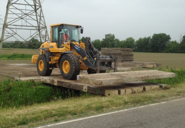
I have been asked to design a temporary construction 'Air Bridge' spanning over a 36" pipeline.

The pipeline owner specifies a minimum 6" airspace; and our span will be 13ft.

The contractor would like to use 12"x12" crane mats for the bridge. The 12"x12" sections are 'sister-ed' together to form 4ft wide mats of varying lengths.

I'm having difficulty calculating a capacity. There are a ton of websites for crane mat suppliers, but none seem to list their actual material types so that I can look up in the wood NDS. They all just say 'hardwood' or 'douglas fir'

Are there industry standards for these mats?

Or should I just assume #3 grade wood with the lowest bending stress capacity?

Or, I can call out a wood grade on the plans?

Crane_Mat_x1cs0n.jpg


Thank you in advance.
 
Replies continue below

Recommended for you

JoelTXCive:
Have the contractor pick a crane mat supplier, and have him get you the name of their best engineering guy, so you have someone to work with, who really knows their product line, and the materials they use. You should probably be careful if the contractor wants to use used mats, that can get kinda dicey, since you have no idea what you will get, and the tension face should be in very good condition since these are spanning, not just soil bearing members. What kinds of loads are you talking about on this 13’ long bridge span, traffic volume, life span, etc.? What are your plans for abutments or end foundations? Does the photo fairly represent the problem you are facing? You do generally want several layers for wheel load distribution to the real spanning layers. Have the contractor look around for some used 13-14’ long steel beams, for four or six stringers for the two main spanning members, then a lighter cross layer of timber matting, and a thin running layer of timber planking in line with the stringers. Add some longitudinal 8x8 curb timbers and you’ve got a bridge.
 
I'd use lowest grade, calculate with Fb/2 but note the drawing to supply wood of minimum Fb.

If this is also for 36" pipeline construction access, its possible to have 18 wheel truck-trailer type pipe carrier or water tanker.

Reality used to affect the way we thought. Now we somehow believe that what we think affects reality.
 
This bridge will be used for a few weeks with construction traffic such as wheeled loaders. The loaders and other misc equipment is down in the 20kip or less load range; although I could have a water truck as -Fourteen mentions.

The bad news is that the contractor has reported back that they need to drive their crane over the air bridge. All the other loads are chump change compared to the crane.

With counterweights installed, the crane weighs 300kips. Without the counterweights, the crane is still 200kips.
The crane has 2 tracks with 50" inch shoes. The tracks are 21ft long.

The pipeline owner wants a factor of safety of 2.

The only good news is that the tracks are longer than the bridge so I don't have to pick up the full load if I have flat approach areas.

I have not done one of these bridges before, but I'm thinking I will not be able to get wood to work. I'm in the steel territory with possible wood decking.

My new question is, if I use W-sections; then what do I do for abutments? Can I set the W-sections in stabilized sand with wood decking and plate steel above?

Or do I need full blown concrete abutments to set the W-sections on?
 
Curious here as to why you're doing this?

Is the pipeline above ground or buried?

If buried, how deep?

There are many ways to assess the ground bearing capacity of buried pipelines from crossing of machinery. Tracked vehicles are usually much better than point load wheels, but enough mats spreads any point loads out to create a uniform external pressure. Unless the ground is going to sink unduly, why is this being required? Is it made of cardboard?

Mats or bog mats as we usually call them are not normally structural things and hence why you're finding it difficult to get data.

If the tracks are 21 feet long to span 13 feet then your bridge shouldn't have an issue. I would ramp it up a little onto and off the bridge so that the crane spends as much time as possible not on the "bridge".

The only time I saw this they used pre cast concrete beams spanning between two concrete beams laid on the ground. This came about due to the inexperience of the engineer in charge of the pipeline. I always thought it was ridiculous and told him so.

Remember - More details = better answers
Also: If you get a response it's polite to respond to it.
 
I'm doing this because I have been instructed by upper management to figure out this air bridge. I believe we have offered to help the contractor out with pipeline and other utility permissions.

Correct, the pipeline is buried. It is a 36" gas pipeline owned by Kinder Morgan. We had the pipe surveyed and it is 6ft below natural grade where we need to cross it.

Kinder Morgan has suggested details for pipeline crossings. But for loads greater than an HS-25 truck, they require a sealed set of plans + calcs for the temporary crossing.

Attached is their suggested detail.

The current status of the project is that we have asked the contractor if they can get a smaller crane.
 
 https://files.engineering.com/getfile.aspx?folder=ef7ef918-8bb5-477d-af7b-12a9bce80b57&file=TYP_AIR_BRIDGE_2_Redline.pdf
JoelTXCive said:
...we have asked the contractor if they can get a smaller crane.

A smaller crane, that remains capable of performing the Contractor's work, could make loading on the crossing higher. Keep all equipment options open until meaningful comparisons of crane footprint loading can be accomplished. When specific equipment choices (make & model numbers) are available is when the Construction Engineering design of the crossing can begin.

[idea]
 
Joel,

You are on the right track with steel beams. With those kind of loads, I wouldn't even consider wood crane mats. I would consider either steel plates or timber decking but would probably lean toward steel plates. Also, you want a concrete abutment. See attached for a sample abutment I did a few years back for an acrow beam bridge. For this one, we precast the abutment and used gracie leveling lifts since it was over a live roadway and installation was time sensitive. For your application, I don't see any reason why you couldn't use CIP abutments. Notice that we used ECO blocks as "wingwalls". You don't have to do this but don't forget about how it is that you are going to retain your backfill on the backside of the abutment. You don't want all your backfill to go "running" away.

One other thing I would consider is keeping the beams from rolling. You may want to anchor them down to the abutment and provide some wood blocking between the beams as a sort of diaphragm. Also, I would definitely tack weld the steel plates down to the steel beams in discrete locations to keep the plates from shifting.

Just my 2 cents...
 
 https://files.engineering.com/getfile.aspx?folder=2081888f-bba9-4841-bb91-9aa1e489c6a3&file=Combined_MB-S02.pdf
Did you check Army construction manual for the design of temporary crossing of heavy armors?
 
You state that the pipe is 6ft below grade. If that 6ft is to top of pipe then you are going to need a longer bridge. If that 6ft is to invert of pipe then I am getting similar 13'-3" span length. But it is important to note that the length is not CL bearing of superstructure but rather edge of abutment.

Untitled9_higrso.png
 
This is all trying to solve a problem which doesn't exist. People have been driving things over pipelines for centuries without all these air bridges. Pipeline codes and standards have this sorted.
See this e.g.

Search on heavy pipeline crossing.

At 6 feet down you really don't have an issue. You can bet KM don't do this when they're working over their own pipelines.....

Concentrating the loads on those main supports creates more issues than spreading it over a wider area

Remember - More details = better answers
Also: If you get a response it's polite to respond to it.
 
Very good reference. This is enough for me.

image_bb8q07.png
 
Good reference LittleInch. Sure does help to put it in perspective.

As much as I hate to do work that isn't necessary, I suspect that this is more about the owner not wanting to incur the liability so passing off the onerous task to the Contractor since their trucks/crane don't really conform to highway, rail, or airport loading. Sounds like the OP would be taking responsibility of the pipe or the bridge one way or another.
 
JoelTXCive:
The worst loading in magnitude is the crane, but they don’t transport that size crane at 300k or even 200k. The counterweights and most boom and mast sections, etc., are transported separately and then assembled on site. Have them walk the crane across the bridge with just enough boom to lift back across for the remaining boom sections and counterweights. This will reduce the crane travel weight below your 200k on about 160sq.ft. of track. What do you know about the soil conditions at the crossing location? KM seems most concerned about any settlement/deflection of their pipe line, which your activity might cause. Then, knowing the specifics on the pipe; dia., thickness, material grade, bedding and installation details, etc. might allow you to make some determination on pipe stresses and settlement potential from your loadings. The two refs. that LittleInch gives in the other thread seem like a very good starting point for your design and engineering report.
 
Status
Not open for further replies.

Part and Inventory Search

Sponsor