It seems easy, yet it’s quite complicated.
Considering a full pipeline (e.g., water) close on both ends and without any venting valve. A drain is opened at a location of the pipe allowing fluid to flow out just by gravity. It is clear that all product in the vicinity and in a higher level than the hole will drain out, but what about the rest? Is there a simple way to evaluate it as well as the final liquid configuration in the pipe?
Furthermore, I’ve thinking about two other points so far: siphon effect and, most importantly, at what point the moved column will generate enough sub-atmospheric pressure to vaporize some of the fluid, like in the example of figure 1 (
Regards
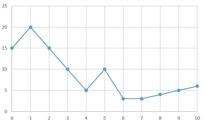
")