Eng-Tips is the largest engineering community on the Internet

Intelligent Work Forums for Engineering Professionals

PIPELINE UPLIFT/BUOYANCY CONTROL

Djidji444

Structural
Mar 11, 2024
17
0
0
RS
Hello,
I have a question for the calculation of buoyancy/uplift on the pipe in the ground during the construction phase of the pipeline (a trench is dug and the pipeline is placed on the ground only). According to the geotechnical studies, the assumption that the underground water level is at the ground level was adopted. My question boils down to whether, after concrete ballasts are adopted to stabilize the pipe, whether there are, in addition to the uplift force acting on the pipe, additional uplift forces acting on that ballast? In translation, in the next picture I drew, is the stability control done according to formula A or B. I come across old projects where it was calculated according to formula A, and it makes more sense to me that it is calculated according to formula B?
viber_image_2024-10-14_18-13-32-963_gau21s.jpg

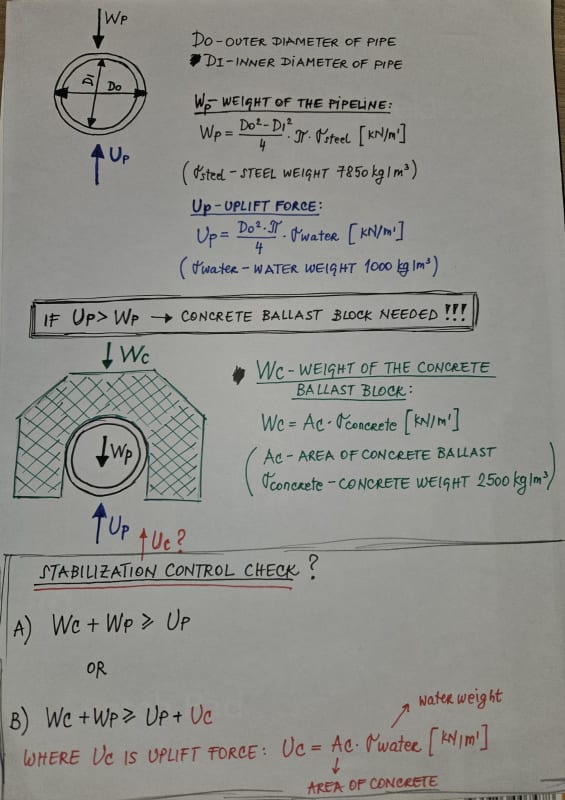
I don't know if it is possible to only take the weight of the concrete block into account without taking into account the additional buoyancy/uplift, only if this is some kind of specific situation, perhaps because this is the construction phase of the pipeline so maybe it is a short period when the buoyancy forces affecting the concrete part are not form, I don't know...

Thanks in advance [upsidedown]
 
Replies continue below

Recommended for you

Could dewatering be part of the excavation and construction process so the water table won't get to the pipe elevation? Are you designing the concrete or are you designing the pipe? This might be better in the pipeline/water/wastewater forum, (if there is one).
 
I am designing concrete block here, therefore, the number of blocks along the entire pipeline route, which directly depends on the buoyancy. And no, dewatering is not part of the the construction process
 
Yes, but it is not the same:
A)the buoyancy/uplift force is lower -> you need smaller concrete ballast
B)the bouyancy/uplift force is higher -> a larger area of ​​concrete (bigger ballast) is needed to satisfy the stability
 
I would say it has to be B because the concrete also displaces a volume of water. If you imagine a lightweight concrete weighing 1000kg/m3 then it would make no difference because it would be neutrally buoyant in the water so you only get any benefit from the concrete by the amount its density exceeds 1000kg/m3. E.g 1500kg/m3 for your blocks.
 
What's going on here???

You only consider doing this in the construction phase if you think the trench is going to fill up with water.

If it is then of course you use equation B because you're only doing because the trench is full of water.

There are other ways of doing this, sandbags and screw anchors to name two.

Are you building this in a swamp?

Remember - More details = better answers
Also: If you get a response it's polite to respond to it.
 
To make it simple you need to take the area of total displacement or discount the unit weight.
The volume displaced by the pipe is your buoyant force. If you take your
concrete weight - water weight = submerged concrete weight

Soil weight-water weight = submerged soil weight

Buoyant force < soil submerged +concrete submerged

Simple solution to this fill the pipe with water and backfill
 
Thank you all for the answers, t is also more logical for me that the answer is B, I just needed confirmation.

And LittleInch, of course, one strives to avoid laying pipelines in swamps, but it is difficult to interpret the data from the limited geotechnical study (plus this is the initial design phase), where in some parts of the route the level of underground water is at ground level in some periods in year. And now it is necessary to estimate how much water can actually occur there, and what I asked above is more a question of a theoretical nature that I was interested in, considering that I come across design projects in which people assume a 'completely submerged state' as an input, and do not take into account all buoyancy forces. Although I repeat, if you take into account so much buoyancy, the amount of concrete ballast would be huge, which is definitely not a realistic situation unless a pipeline is being designed in a swamp. Therefore, it is always necessary to adequately assess the amount of underground water, although it is difficult based on insufficiently precise geotechnical data.
 
That's why you don't normally try and install a buried pipeline in areas of high ground water table at those times of the year.

If you have to then you either work on de watering the ground around the trench, pumping put the trench water out until you can backfill the pipe, add concrete coating to the pipe like they do offshore for exactly the same reason. Screw anchors to hold the pipeline down are used in many swampy locations for long term stability if the backfill is basically swamp like muddy water.

Problem with concrete weights are they tend to sink in the goo and your line slowly sinks over time, especially when you then fill it with liquids.

I forget the crossover point, but its around 20-24" where a standard wall thickness pipe (10-12mm) starts to become buoyant when empty.

Concrete dog houses would probably be needed for about 20-30% of the length of the pipeline if you tried it that way, hence why you don't see it very often.

Remember - More details = better answers
Also: If you get a response it's polite to respond to it.
 
In Lousiana, East TX and a lot of Minnesota, we didn't have a choice. We would excavate a Trench and it would fill with water in minutes. Nowhere to pump it out either. It would just fill up again, this time with mud. Water everywhere.

I seem to remember it's more like 6.625OD std @ 19 plf. I get buoyancy of 15 plf.
I always used 125% x buoyant force as a minimum pipe + weights or coating to guarantee it will sink to the trench bottom in mud. That is especially needed if its an offshore pipeline being lowered with a jet sled. You can get a lot of mud in the Trench. DNV says 110%, but that is only working in clear water. Other company specs I see are 120%. If bare, the 6" std is 126% of buoyant force in fresh water. So a 6" STD is my not-buoyant cutoff. Lighter wall 6" will float in mud. An 8" std wall will probably be less than 125% of buoyant force.

If you design for 125% buoyancy, it's pretty much neutral in mud, so it's not going to do much sinking and it is enough safety factor until you get complete liquifaction, if you happen to be in a seismic zone.

--Einstein gave the same test to students every year. When asked why he would do something like that, "Because the answers had changed."
 
It might easily be a bit smaller diameter - been a while since I've done this, but its easy to do.

Swamp installation is a work of art alright - I don't envy anyone doing it.

It's the difference between keeping it there when empty and not sinking when its full of water for the hydrotest or in use that's the fun part.

Remember - More details = better answers
Also: If you get a response it's polite to respond to it.
 
Gas lines need a quick hydro.

Screw anchors are more convenient than lugging around saddle weights.

--Einstein gave the same test to students every year. When asked why he would do something like that, "Because the answers had changed."
 
I'm just not sure how to treat the buoyancy force as a permanent or variable load, according to Eurocode standard(UPL load combination)?

This seems to be a topic of discussion for many people, but more often than not I find it being treated as a permanent load. The safety coefficients with which the loads are multiplied are different, the permanent-stabilizing load is reduced by multiplying by 0.9, while the destabilizing effect (buoyancy) is multiplied by 1.0 (if it is permanent) or by 1.5 (if it is variable). And okay, this 1,0 coefficient (for permanent load) is increased by the national annex to 1.1. But the assumption that the groundwater level is level with the ground (which can happen in some period of the year) and that the buoyancy increases 1.5 times, leads to an unreasonable large amount of concrete ballast blocks, and comes down to a continuously ballasted pipeline route, which does not make sense, it is only a short-term construction phase.

Maybe if it is estimated that the groundwater level is at ground level, it can be treated as permanent load, with a lower coefficient, and alternatively, if the groundwater level is lower, the buoyancy can be treated as a variable load, I don't know.
 
It seems that you trying to apply structural engineering criteria to pipeline design. Of course that isn't going to get any reasonable answers.
Pipeline design codes do not factor loads. Load combinations are real. Not all live loads need be combined to 1 case; only those combinations that can occur need be considered. Safety is provided by reducing allowable stress.

Assume dry conditions first.
Check uplift during buoyant conditions with groundwater equal to ground surface.
Ground surface is used to capture any possible reduction of soil or other weightings above the pipe that might be considered to provide stability against floatation during buoyant conditions.
Use a safety factor against flotation of (IMO) 1.25 for any buoyant design scenario.
I would use 1.25 as the safety factor, first checking the pipe alone, ie without saddles weights.
(If I used a lower SF than 1.25, I would also reduce weights of saddles to 90%.)
If not meeting the safety factor against flotation, provide saddle weights.
If there is reasonable chance for future soil saturation, leave the saddle weights in place. If not, then remove them only after dry conditions are permanently established.


--Einstein gave the same test to students every year. When asked why he would do something like that, "Because the answers had changed."
 
I still don't know what you're trying to find or really why a structural engineer in getting involved in pipeline design and construction about which you appear to be inexperienced.

If in construction your trench rapidly fills with water before you can backfill the trench, the pipe can easily start to float, which is not a good thing.

There are many ways to resolve this, only one of which requires concrete blocks as you could need a lot of them. Screw anchors are a lot better in many ways, but sometimes partial back fill, sandbags, concrete mattresses, concrete coating, water removal / dewatering can all be considered depending on your local conditions, soil properties, water level etc etc.

So long as the ground, whether saturated or not, is seen as sufficiently strong to resist uplift, no permanent blocks are required. Only where the soil is very weak (swamp, silt, muddy water) do you normally look at more permanent ways to prevent uplift and floating of the pipeline once installed.

as my colleague mr 44 says, you normally look at a factor of 1.1. to 1.25 against floating or uplift if the soil is weak and saturated or to prevent floating before backfill.

Remember - More details = better answers
Also: If you get a response it's polite to respond to it.
 
I completely agree, but the situation is such that this part of the pipeline calculation is given to the structural engineer, whether I want it or not, it is even necessary to adjust the calculation to some extent to structural engineering standards, that's why my questions are more inclined to structural engineering. And instead of pipeline design being handled by one multidisciplinary person, as is probably the practice for all of you and as it should be, the current practice here is to divide the pipeline design into several different engineering professions (structural, mechanical, electrical etc.). And of course, in the desire to learn this topic, which is less familiar to me, and to do at least my part of the job properly, I ask around and learn as much as I can, therefore also the questions on this forum.
By all means, thanks for all the answers and discussions, you help me a lot [upsidedown]
 
Are you in Serbia?

I'm not being disrespectful here, but you are correct, that's a strange way to build pipelines in the rest of the world. Might be hangover from the Yugoslavia days, but hope you've got the drift now.

Still basically a construction issue unless your soils are really bad.

If so then just concrete coat it is probably the easiest way to handle this. Those concrete saddles have a tendency to be dropped on the line or create point loads / dents / coating damage and are hence not commonly seen.

Try the pipelines forum next time maybe as this is not a classic structural issue.

Remember - More details = better answers
Also: If you get a response it's polite to respond to it.
 
No, but definitely an ex-Yugoslav here, but I don't want to throw my country under the bus here now. Unfortunately, a smaller country with a poorly structured system and excellent, but underestimated engineers. In the future I will look at pipeline forums too, thanks :)
 
Back
Top