Eng-Tips is the largest engineering community on the Internet

Intelligent Work Forums for Engineering Professionals

  • Congratulations waross on being selected by the Tek-Tips community for having the most helpful posts in the forums last week. Way to Go!

Piping inlet for vertical tanks

Status
Not open for further replies.

artome

Mechanical
Mar 11, 2013
5
0
0
PT
Hi,

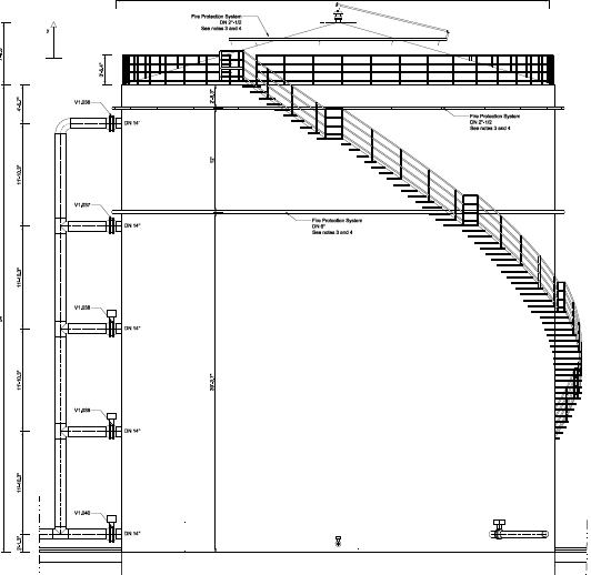
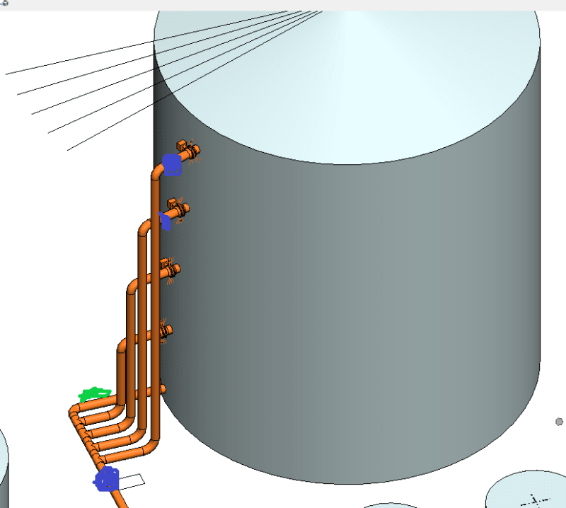
I am designing a piping layout for a project which connects to various tanks. As per client's specifications they want a communal vertical shaft with inlet/outlets at various levels of the tank to be able to extract the fluid depending on decantation levels.

One of the tanks' vertical shaft is about 15 metres tall and has 5 branches at a n interval of 3 metres. the other tank has a vertical shaft of 12 metres with 5 branches every 2.5 metres.

My problem is that the resulting axial thrust force from the lowest branch and the bending moments of the branches further up the shaft are too great for the nozzle connection.

My question is two-fold:

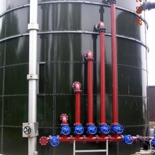
1) Is this type of inlet usual? From all I've seen there is usually only 1 pipe for 1 inlet.

2) How can I relieve these values?

Thanks in advance!
 
Replies continue below

Recommended for you

Can you add a drawing or sketch of this arrangement?

Remember - More details = better answers
Also: If you get a response it's polite to respond to it.
 
In a lot of cases, an arrangement like this would simply be detailed up without any detailed stress analysis of the piping or of the nozzles.

One consideration is to make sure the analysis includes the flexibility of the nozzles. If a "fixed" nozzle was assumed in the piping analysis, then much of that load may go away when the flexibility is considered.

If necessary, you could introduce flexible couplings below each T connection and eliminate some of the loading.

As a side note, keep in mind that the tank changes radius depending on product depth and temperature, and also gets shorter when it is filled (hoop stress plus Poisson's ratio gives shortening in the vertical direction). Nozzles near the bottom of the tank will also rotate up and down slightly with product level.
 
This sounds similar to what used to be called a Bridle or Stand Pipe ...... We ancient piping engineers used to specify these as a place to located and maintain various instruments for tanks.


I have personally seen installations that were so heavy that the stand pipe had to be supported independently from the tank.

What operating temperature are we talking here ?

A sketch would certainly help ......

MJCronin
Sr. Process Engineer
 
Hey guys,

Thanks for the prompt replies. The type of installation I am trying to describe is as follows from the image shown. It is a communal vertical pipe that has horizontal branches going into the storage tank.

Screenshot_2018-12-02_at_20.40.48_k0zjxz.png


Thanks!
 
I have never seen anything like this .....How fast must you decant ?

IMHO, Based on your drawing, the decanting piping looks very large ...(12"NPS ?/... 14"NPS ????? .... Larger ???)

If the solids laden liquid must sit for a while, you probably can get by with a smaller diameter piping system.

Use more reasonable smaller diameter piping (with proper pipe supports)and your nozzle problem goes away .....


MJCronin
Sr. Process Engineer
 
I have to ask this question ....

What happens after your giant tank is filled (nearly to the rim) with solids ? ..... How does this work ??

I assume solids must be cleaned out from the tank eventually ...

i have designed and specified decanting ash handling tanks for Waste-to-Energy plants, but we would never include decanting nozzles higher than about 1/3 of the way up the shell.

We would also include "tombstone" access doors low in the shell and a large roof hatch to lower maintenance equipment from above

MJCronin
Sr. Process Engineer
 
I've seen this lots of times on liquid storage tanks. No big deal, you are perhaps over thinking this. There will be very low stresses on the tank shell and most can be totally avoided if you put a pipe support under the riser. If you can't put a pipe support there, add diagonal braces to support the pipe and take loading off the nozzles. If your pipe stress program shows high axial loads, add an expansion joint just before the riser. Use any flange you feel like, and standard API shell nozzle details.
 
Is it usual - No, but not unique.

The issue you have is lack of support but also you have issues with multiple nozzle, pipe expansion and tank deforming during filling.

So you need to either make the riser more flexible by maybe adding a 90 degree horizontal arm from the tank nozzle which then connects into the riser or maybe making the connection from the riser to the tank by some sort of flexible or bellows type arrangement. And support the base of the riser from the tank foundation or connected tot he tank foundation so you don't get differential settlement of tank base and riser support base.

Remember - More details = better answers
Also: If you get a response it's polite to respond to it.
 
To all,

Thanks for the input so far. The sketch I sent didn't have the supports but in fact I do have 1 just beneath the riser (this is the technical word which was unknown to me until now). Despite that, and extrapolating nozzle stiffness values from API 650 (the graphs from appendix P don't show L/2a values for over 1.5), the moments I get range from 27kNm to 80kNm (moments in the lift direction) which, from the tank manufacturer's point of view are too high.

I tried to limit the moments with supports with no upward gap but this just increases the force in that segment (axial thrust of 80kN).

The problem with this installation is lack of space. Also the client does not want expansion joints. This with a dT of 60ºC leads to some ridiculous values I've been trying to mitigate. In my attempts at changing the layout I decided to separate the risers to one for each nozzle, as shown from the image below:

new_layout_t1.3_tjbmwd.png


The smudges in blue will accomodate a vertical stop support, whereas the green will also have a lateral guide to limit the moment in that direction. The results with this layout are tremendous, with values below 10kNm, but now my question is if this is a viable solution (and I will also have to verify with the client), especially considering the height of the supports near the nozzles. I was wondering if the tank designers can accomodate this. Is this a viable solution?

Regards
 
Have you tried moving the vertical pipes as far from the tank as possible, or as close as possible with valves in the vertical?
 
Status
Not open for further replies.
Back
Top