Eng-Tips is the largest engineering community on the Internet

Intelligent Work Forums for Engineering Professionals

Pivoting table top lifting mechanism

Status
Not open for further replies.

roshane87

Mechanical
Mar 14, 2015
21
0
0
LK
Good Day to you all,

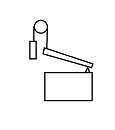
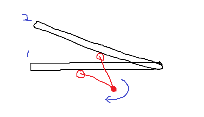
I have a project where I have to convert a table which is currently fixed with the top at about a 25 degree angle with the horizontal to one which can be flat or 25 degrees.

I'm still at the early stages of design and don't know the exact weight of the top but it's about 18.3m long and 1.5m wide made out of 1.5" (38mm) square tube. I'm assuming 1 metric ton (overestimate) as the table has a glass top + a motorised cart working on top of it.


My biggest concern is how to make it change the angle using a manual method. The customer doesn't want it powered.

As it's quite long, I am concerned about how tolerance stack will contribute to the level of the table across the length when lifted.

I'm planning on resting it on supports when flat so the straightness of the tabletop when flat shouldn't be a problem.

Below is a rough model showing the two positions. I initially thought of using my own screw jack setup but I'm wondering if there is a more economical and effective method instead?


Looking forward to seeing what other ideas you might have to achieve this.

Cheers,

RN


RN
 
Replies continue below

Recommended for you

Hydraulics would allow you to drive several lifts at the same time. Mechanically linking the various lifts would be problematic.

and hydraulics would give you the mechanical advantage I think you'll need (to hand control the possibly 1 tonne table).

another day in paradise, or is paradise one day closer ?
 
Hi

How about several shafts connected along the length of the table with several pairs of spur gears and a winding handle at one end.

“Do not worry about your problems with mathematics, I assure you mine are far greater.” Albert Einstein
 
desertfox : it is exactly what I understood in the sketch view. For me it becomes a problem of torque on the wheel by one man (and should not be auto-reversible motion)
 
Budget?

Can there be overhead mechanisms?

Overhead, counterweighted chain lifts come to mind. Understanding that the counterweights need to be sized for up and down motion loaded and unloaded. Still requires power, either human or otherwise.

gizmo1_fk4ydj.png
 
Hi robyengIT

Yes I agree at 18m long it’s not going to be easy, there would be significant wind up in shafting that length too.

“Do not worry about your problems with mathematics, I assure you mine are far greater.” Albert Einstein
 
1) Disagree on hydraulics. Why? Because your table is too long to be very stiff, and hydraulics, though powerful, is very difficult to synchronize. You want each lifting point to move the exact same amount, and that can be difficult to achieve for a low cost with hydraulics. I've done it. And that's why I would recommend other means.

2) I would recommend an arrangement similar to what you show. Driving multiple mechanical jacks from a single long torque tube is a proven method, as long as that tube is stiff enough to resist any significant angular deflection. Of course you would have to arrange some gear reduction at the manual input point to accommodate human limitations.

3) Another approach would be to attach steel cables to each support point. Run them up and over a pulley at each station, then horizontally to a single four-cable winch drum at the input crank driven manually. Kind of hokey, but its cheap and it could work.

4) You could mix two of the above approaches. Run a large diameter torque tube the full length of the table. Attach those cables to each support point. Then run them up and around that torque tube using it as a winch at each station.

There are a thousand ways of skinning this cat. I have found roller chains are often overlooked as very useful power transmission devices. Get creative.
 
here kittie, kittie, kittie ...

I think an 18m torque tube is going to have to be bejesus stiff to transfer the load. The 2nd problem is going to be developing the required mechanical advantage, something like 1000:1.

one way to make it easier would be to rotate about the mid-point of the table (rather than the obvious edge). This will 1/2 the travel and reduce the work done enormously.
and give you two inputs (one to raise, the other to lower) at opposite sides of the table, allowing the controlling arm/linkage to always be in tension

another day in paradise, or is paradise one day closer ?
 
Good Day to you all and thank you for your replies,

Using Hydraulics is not an option. As I mentioned before, it cannot be powered in any form and also Hydraulics would not be very suitable due to the mess it can make if a hose bursts for instance.

As JBoggs mentioned, there are many ways to skin this cat. Just trying to work out the best (effectiveness + cost)

rb1957 what you say sounds interesting but I'm not sure what you mean by two inputs? Would you please elaborate when you have some time?

So another thought I had was to use a cam mechanism to raise/drop the table the required 250mm. Planning on using the same torque tube along the length but have an arm with the roller at the end of it which contacts the 38mm square tube and moves it up or down. I can drive from the centre of the table using a worm gearbox with the torque tubes running either side.

image_gsz32l.png


As per my rough calculations, to have a negligible (< 2 deg) twist on the torque tube, I'm guessing I need at least a 63.5mm (2.5") torque tube. Can anyone else confirm this for me please?

image_egigby.png


Looking forward to hearing your responses.

Thank You,

RN
 
Hi

In the calculation you have posted the tube radius is 63.5mm therefore the tube diameter would be 127mm diameter quite a chunk of metal, I thought you meant a tube diameter of 63.5mm before I saw the calculation.
Really the torque can’t be calculated with any accuracy until you know the actual mass of the lid and it’s centre of gravity.

“Do not worry about your problems with mathematics, I assure you mine are far greater.” Albert Einstein
 
Thanks for pointing that out desertfox. Saved me a lot of blushes later if I considered that as the radius.

Does anyone have any alternate ways of achieving this though?

RN
 
Hi Rostand87

You’re welcome, is it possible you can split the top into two pieces and operate them independently? Or does the whole thing have to lift or close all in one, if the former is an option that would make it easier to use a torque tube for each half.

“Do not worry about your problems with mathematics, I assure you mine are far greater.” Albert Einstein
 
Compliance, say rubber mounts, in each of the jacks would allow each of the jack/rubber mount outputs to apply more even loads. In theory, if you look at the compliance of the torque tube you could figure out how stiff each of the rubber mounts needs to be. Of course there's also backlash...
 
Roshane87:
I would make the table surface stiff enough to carry the load and to work as a work surface/platform for whatever you are doing. Then, I would pivot it on, a hinge or pins, at its mid-width, at 1.5/2 m, at each of the 7 leg frames. Now, when you want to rotate/tilt it, it takes much less work or force. The tilting mechanism must extend on one side and contract by the same amount on the other side, for some support out near the edge of the table top. While I haven’t spent much time detailing this; this might be accomplished by a single central shaft with a large gear at each leg structure, which works as a rack and pinion, lifting one rack while lowering the other by the same amount, maybe a chain drive btwn. the two pinions. In any case, the load you are now trying to manipulate is the eccentricity of the load and table top about the hinge line.

Edit: When your boss or client asks you to move a mountain, but then says don’t use any real power to do it, other than a wish and a feather’s touch, you do have the right to tell them they are crazy.
 
Hi desertfox, ideally the 18m needs to pivot as one unit.

dhengr, I have drawn in a screw jack mechanism with a common shaft. The pivoting end will be hinged. I was looking for different solutions/ideas to my one of using a screw jack which might be more effective and cost less.

RN
 
Status
Not open for further replies.
Back
Top