canwesteng
Structural
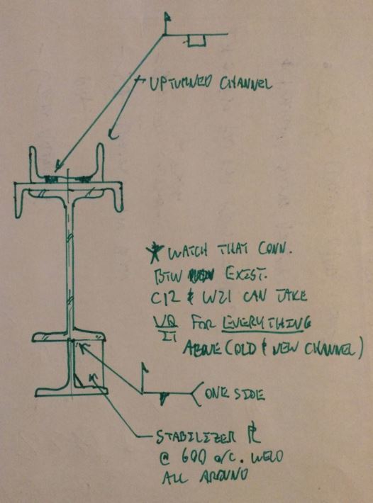
We have an issue where we welding in an area with little access. I have come up with the attached detail, but I believe it requires pre tacking a backing bar to the tee being welded to the wide flange, or pre tack it to the wide flange. Is this acceptable?