Continue to Site

Eng-Tips is the largest engineering community on the Internet

Intelligent Work Forums for Engineering Professionals

  • Congratulations waross on being selected by the Eng-Tips community for having the most helpful posts in the forums last week. Way to Go!

Plate Buckling coefficients 3

Status
Not open for further replies.

Capko

New member
Feb 16, 2016
25
Hello everyone,

Does anyone know how can I obtain the equation of the buckling coefficients for a composite plate ?. I want to know the function of this kind of chart :

plot%20of%20critical%20buckling%20coefficient.jpg
 
Replies continue below

Recommended for you

See NACA TN 3781 Equation 48
kc = ((a/mb ) + (mb/a))^2
 
Sorry, I missed that you were asking for a composite plate, if you are able to get a copy (though as far as I can tell it's not publically available via the NASA website) you should have a look at:
DoD/NASA Advanced Composites Design Guide Table 2.2.2.I

 
I don't know if there is a simple answer to your question. The buckling behavior of a composite plate should depend highly on the specific layer arrangement, etc. Depending on the type of composite you are dealing with the stiffness matrices will vary.

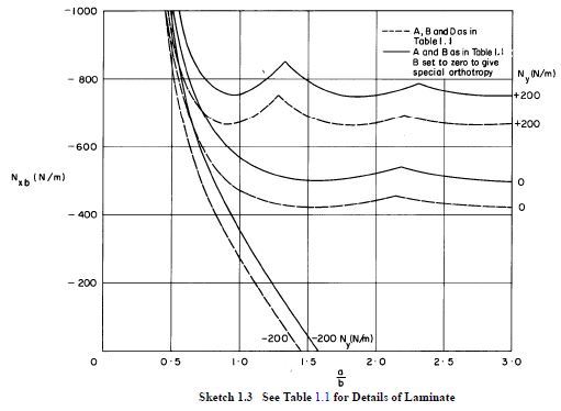
I found some curves from ESDU 94006. But these are specifically for plates where small deflection theory is applicable, because of the effect of bifurcational buckling. Also the results are not a coefficient, but an actual buckling load calculated based on a computer script. The result shows that the behavior is similar. I would recommend reading this document if you can find it as it has some good theoretical discussion.

1_ekslrr.jpg


Keep em' Flying
//Fight Corrosion!
 
For an isotropic material with a unaxial stress (or running load), the function of the chart is to pair the coefficient with the stability equation Fcr=(Pi^2*Kc*Ec*(t/b)^2)/(12(1-v^2)). This can be done for various edge conditions, but that chart is for all edges simply supported. An isotropic material has 2 independent elastic constants, which are part of the equation.

On the other hand, a composite laminate has at least 4 independent elastic constants that affect the stability solution (D11, D22, D12, D66). This is assuming the laminate is balanced, that bend-twist coupling is minor, and that the transverse shear stiffness does not affect the solution. In the event that the laminate is unsymmetric, the D* components are preferred.

So rather than use a chart that gives you a coefficient, you can solve for the following equation for composites. The simple case for uniaxial loading and all edges simply supported is in MIL-HDBK-17, CMH-17, and various other publications. If you were to solve this equation for an isotropic material, you would see that you will be able to back out the Kc values and they are identical to the chart you attached. That is actually how the charts are developed (backing out coefficients from the analytical solutions - if available).

plate_uz8p16.jpg


Brian
 
Status
Not open for further replies.

Part and Inventory Search

Sponsor